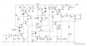
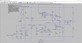
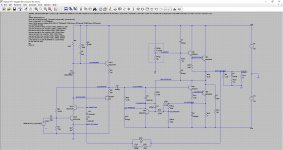
Hi All, I came across a Sugden A21 mod circuit in the net. Quickly I input and simulate it in ltspice. The result is surpisingly good. I understand that it is not the original A21 series 2 circuit, so is it possible to add a mosfet/jfet differential front end and dual rail supply to get rid of the output capacitor?
Feel free to download and play with the attached .asc, any feedback and idea are more than welcome😉
Feel free to download and play with the attached .asc, any feedback and idea are more than welcome😉
Attachments
If you add a differential input stage you will totally destroy the magic that makes a design such as this sound as it does.
If you want a split supply and DC coupling then add a DC servo to set the bias point.
If you want a split supply and DC coupling then add a DC servo to set the bias point.
This particular Sugden amp can benefit from a significant power supply upgrade - I'd suggest some thought about the output cap too.
As Mooly said, this amp just sounds like it does - don't stuff with it.
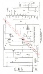
There are other Sugden circuits that operate with differential rails if you want to play with them ...
As Mooly said, this amp just sounds like it does - don't stuff with it.
There are other Sugden circuits that operate with differential rails if you want to play with them ...
If you add a differential input stage you will totally destroy the magic that makes a design such as this sound as it does.
If you want a split supply and DC coupling then add a DC servo to set the bias point.
Hi Mooly, thanks for your input, I guess I do not implement DC servo correctly in the attached circuit. Can you suggest a way to connect the DC servo for the SRPP output stage?
million thanks!😀😱
Attachments
Thanks James actually I just want to get rid of the output cap, especially if the differential front end may deteriorate the sonic quality.This particular Sugden amp can benefit from a significant power supply upgrade - I'd suggest some thought about the output cap too.
As Mooly said, this amp just sounds like it does - don't stuff with it.
There are other Sugden circuits that operate with differential rails if you want to play with them ...

I hate to say this but that output cap is part of the sound - Sugden did produce an amp with differential rails and hence, no output cap - naturally, they do sound different to the '21' but if you want to change that sound, then maybe start with their newer reference amps ….
If you add a differential input stage you will totally destroy the magic that makes a design such as this sound as it does.
A rather unexpected view. I agree.
I find the original design better.
I would
use a JFET in the place of T1 keeping T2
omit T3, T4 and the voltage regulator (it compromises the single-ended character). The input stage and the VAS would need a clean power supply.
omit various diodes and capacitors.
I also find the arrangement around the VAS muddy.
Hi Mooly, thanks for your input, I guess I do not implement DC servo correctly in the attached circuit. Can you suggest a way to connect the DC servo for the SRPP output stage?
million thanks!😀😱
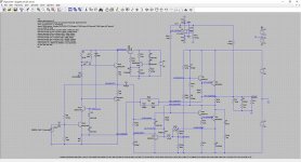
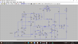
The servo has to act on TR6 and TR7 rather than the current regulator. You can also remove R19 and R20. The opamp should be a FET type and doesn't need R17. R24 needs to be able to supply sufficient base current for the pair.
Attachments

A rather unexpected view. I agree.
I find the original design better.
I would
use a JFET in the place of T1 keeping T2
omit T3, T4 and the voltage regulator (it compromises the single-ended character). The input stage and the VAS would need a clean power supply.
omit various diodes and capacitors.
I also find the arrangement around the VAS muddy.
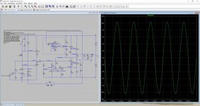
Here attached is the ltspice circuit, please feel free to modify it and share with us 😀

Attachments
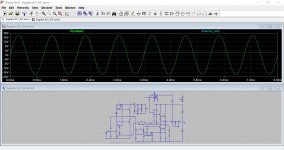
The servo has to act on TR6 and TR7 rather than the current regulator. You can also remove R19 and R20. The opamp should be a FET type and doesn't need R17. R24 needs to be able to supply sufficient base current for the pair.
Thank you Mooly, it works very well in simulation, I will try to see if I can find some OEM to make some prototype.

Attachments
The output of the servo circuit sees the full output signal swing. This will not work but probably kill the opamp through the 1k output R.
Servos should safely work at low levels and inject the correction signal at the input side where levels are low.
Jan
Servos should safely work at low levels and inject the correction signal at the input side where levels are low.
Jan
Hi Jan,
The servo only seems to see a current swing of around -/+1ma at its output at full voltage swing, the AC voltage swing is just a few millivolts... and which is what the sim shows, but I see where your coming from.
I wonder if the bootstrap and the relatively high feed resistance from the opamp plays a part there.
In any case, the -/+20 volt rails allow for suitable opamps to be used directly... but yes, a bit of a puzzle.
Attachments
The gain from opamp output to amp output is just 1. Normally you have just a fraction of a volt servo output to a point forward in the amp to have enough gain to keep the offset low. Also there is the full amp output as common mode on the opamp output via the 1k. I understand you need the 1k instead of the customary 10k or 100k because of the low insertion impedance.
I haven't done the sim but after 40+ years of designing amps all my alarm bells go off.
But then again, no guts no glory ;-)
Jan
I haven't done the sim but after 40+ years of designing amps all my alarm bells go off.
But then again, no guts no glory ;-)
Jan
The gain from opamp output to amp output is just 1. Normally you have just a fraction of a volt servo output to a point forward in the amp to have enough gain to keep the offset low. Also there is the full amp output as common mode on the opamp output via the 1k. I understand you need the 1k instead of the customary 10k or 100k because of the low insertion impedance.
I haven't done the sim but after 40+ years of designing amps all my alarm bells go off.
But then again, no guts no glory ;-)
Jan
Hhaha thanks Jan, that's true too. Maybe we can use a multi turn VR to set the required voltage for TR6.
Attachments
Last edited:
Hhaha thanks Jan, that's true too. Maybe we can use a multi turn VR to set the required voltage for TR6.
That will work but not track with temperature, so will drift.
Why not insert the servo output via 100k to TR10 base? I haven't checked the polarity so maybe you need to move to TR10 emitter for correct polarity, but that would most designers do.
Jan
That will work but not track with temperature, so will drift.
Why not insert the servo output via 100k to TR10 base? I haven't checked the polarity so maybe you need to move to TR10 emitter for correct polarity, but that would most designers do.
Jan
It is because there is a coupling capacitor c9, so DC servo wont work at TR10.
this is class A amp, the operating temperature is near constant . So servo is not a must.
By referring the output lower stage to Vee instead of ground and suppressing the voltage regulator referenced to ground , you introduce very high PS ripple and noise . Following my precedent advise it can be reduced but not eliminated due to local feedback of the input stage.
By referring the output lower stage to Vee instead of ground and suppressing the voltage regulator referenced to ground , you introduce very high PS ripple and noise . Following my precedent advise it can be reduced but not eliminated due to local feedback of the input stage.
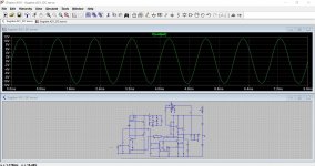
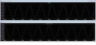
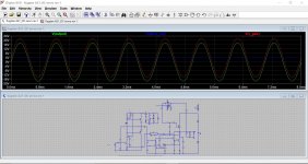
I've noticed that with the circuit in standard form (R19 and R20 connected) that the output clips at just -/+ 7 volts swing. Adding the servo removes that limitation. Weird!
But then again, no guts no glory ;-)
Jan
Oh yes 😀
I think I've finally got a handle on how this appears to work. The key is the 'bootstrap' that is able to add the output voltage to the servo correction value.
In this example I've replaced the upper transistor pair with a FET and increased the servo feed resistor to 10meg.
Attachments
- Home
- Amplifiers
- Solid State
- Sugden A21 clone modification