Is there such thing as too much capacitance?
If so, how to calculate / select the right amount of capacitance?
If so, how to calculate / select the right amount of capacitance?
Hi,
I have only just recently found out here on DIYaudio that the PSU RC time constant is related to the global NFB and input time constants.
input RC << NFB RC<< PSU RC(filter caps *nominal load )
eg. input 100mS ( F-3db=1.6Hz), nfb 140mS, psu 200mS,
you can even spread them out to one octave spacing.
Gives you something to try.
AndrewT said:Hi,
I have only just recently found out here on DIYaudio that the PSU RC time constant is related to the global NFB and input time constants.
input RC << NFB RC<< PSU RC(filter caps *nominal load )
eg. input 100mS ( F-3db=1.6Hz), nfb 140mS, psu 200mS,
you can even spread them out to one octave spacing.
Gives you something to try.
Hi Andrew,
This is new for me. Where is that based on? Any engineering type backup for that idea?
Jan Didden
Yes you can have too much capacitance in a PSU. Higher capacitance means higher and shorter charging current spikes. They can be high enough to damage rectifier diodes (especially Shcottky diodes, which tend to have lower ratings) and radiate a lot of EMI.
How much to choose? The minimum value is bounded by how much ripple and rail sag you can put up with. The upper value is bounded by the aforementioned current spike value and how much you are willing to pay. The easiest way of working it out is to simulate it (being sure to include the effective impedance of the transformer).
How much to choose? The minimum value is bounded by how much ripple and rail sag you can put up with. The upper value is bounded by the aforementioned current spike value and how much you are willing to pay. The easiest way of working it out is to simulate it (being sure to include the effective impedance of the transformer).
Hi Jan,
it was news to me too. I went back to some old amps and found that the time constants were somewhat random.
At least two contributors suggested the staggered RC time constants & their reasoning sounded logical. Although they did not use the word Motorboating I think they were alluding to this.
Mr Evil, a small series R before the rectifiers reduces current spikes enormously.
You can do that, but you lose a lot of efficiency and regulation.AndrewT said:...Mr Evil, a small series R before the rectifiers reduces current spikes enormously.
Mr Evil,
How do you simulate the amount of capacitance needed?
The only test instrucment I have is a Digital Multimeter, Fluke 189. Measure the usual + capacitance, frequency.
How do you simulate the amount of capacitance needed?
The only test instrucment I have is a Digital Multimeter, Fluke 189. Measure the usual + capacitance, frequency.
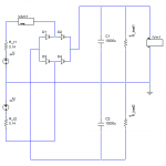
I mean using a circuit simulator, such as Spice or whatever (there are free programs you can use: searching the forum should turn something up). For instance, the attached picture is what a test circuit might look like in the program I use. V1 and 2 represent the voltage out of the transformer, with R_t1 and 2 approximating the impedance of the transformer (you can work that out from Ohms law, the unloaded and fully loaded output voltage and rated current of the transformer).gengis said:Mr Evil,
How do you simulate the amount of capacitance needed?
The only test instrucment I have is a Digital Multimeter, Fluke 189. Measure the usual + capacitance, frequency.
Do a transient analysis and observe the current and voltages. Make sure the output voltage has low enough ripple etc, and that the currents don't exceed any device ratings.
Attachments
- Status
- Not open for further replies.
- Home
- Design & Build
- Parts
- Such thing as too much capacitance??