I am making my first subwoofer, and my goal is really to understand the physics of what is happening. I am happy to get advice on rules of thumb that end up generally producing good loudspeakers, but I would really appreciate advice on how to methodically understand what is happening as I fine tune my design despite not having an anechoic chamber.
I bought a Umik-1 Calibrated Microphone and a DATS-V3 for this project. Before I started I thought the process was:
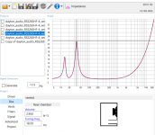
During my build I ran into some problems. Specifically on step #7. I got an impedance graph where the resonate frequency seemed to be right, but the magnitudes of the impedance were not scaled as I expected. The observed peaks were twice as large in magnitude, as the simulated peaks.
Question 1: Is it reasonable to expect the impedance to match between simulation and real life? Can the room change the impedance?
Question 2: Is there a way to measure Ql, Qa and Qp once you have built an enclosure? I noticed that varying these three quantities could shape the impedance of the speaker, but in order to match simulation vs reality I had to use insane values (QI=1000, Qa=1000, Qp=5) whereas I am told (QI=10, Qa=100, Qp=100) is more reasonable.
I bought a Umik-1 Calibrated Microphone and a DATS-V3 for this project. Before I started I thought the process was:
- Simulate a cabinet that achieves the response I want based on the manufacturers published specs.
- Buy the driver, break it in and measure its actual T/S parameters
- Adjust the simulated enclosure dimensions, port length, etc to achieve the desired response.
- Build the enclosure.
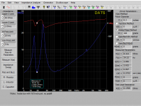
- Test the loudspeaker in two ways (A) with a measurement microphone. Keep the microphone very close to the driver to reduce the effect of room reflections. (B) Test the impedance of the loudspeaker.
- If you are happy with the loudspeaker you are done. If you are not happy continue.
- Adjust the simulation so that it agrees with the results from step #5, this likely involves tweaking the port length, volume of the box, and Ql, Qa and Qp.
- Once you have this more accurate model of the loudspeaker you can make variations of that model to find something that should have a better response, return to step #3.
During my build I ran into some problems. Specifically on step #7. I got an impedance graph where the resonate frequency seemed to be right, but the magnitudes of the impedance were not scaled as I expected. The observed peaks were twice as large in magnitude, as the simulated peaks.
Question 1: Is it reasonable to expect the impedance to match between simulation and real life? Can the room change the impedance?
Question 2: Is there a way to measure Ql, Qa and Qp once you have built an enclosure? I noticed that varying these three quantities could shape the impedance of the speaker, but in order to match simulation vs reality I had to use insane values (QI=1000, Qa=1000, Qp=5) whereas I am told (QI=10, Qa=100, Qp=100) is more reasonable.
Attachments
Question 1: Yes and yes.
Question 2:
Ql, the system's Q at Fb due to leakage losses (sealing of the cabinet, etc.) can be checked by listening for air leaks. A light coating of dilute soap may show bubbles forming around air leaks.
Qa, the system's Q at Fb due to absorption losses could be checked by removing any fill (fiberglass, foam, polyfil, wool, etc.)
Qp the system's Q at Fb due to port losses (turbulence, viscosity, etc.) could be checked by testing at different input levels.
Observation on #5: If the microphone very close to the driver to reduce the effect of room reflections, it may not "hear" the port response.
For example, if a driver was measured 2" from the center of the cone, and the port was located 8" from that point, the port contribution would read about -12dB lower (each doubling of distance reduces SPL by 6dB in a free field) than if the mic was in the far field. Far field for a sub of your size can be as little as 1 meter, depending on port/driver placement. This could be the reason for your "Unexpectedly Steep Drop Off on Low End" observation.
That said, as Just A Guy mentioned yesterday, the room can have as much effect on measurements as the speaker at subwoofer frequencies, best to measure outside.
Art
Last edited:
It's curious that you're measured impedance peaks are higher than the sim says they should be. That suggests that there's an error in the sim technique. OTOH, if they were lower, that could be mainly due to losses not counted for in the sim.
As you can see from the rest of the sim'd impedance curve, it's not a really good match for the measured one. For a better match, you need to use a sim tool like Hornresp and use the driver's measured semi-inductance parameters in the sim. Using these parameters should also provide a more accurate sim for the frequency response of your build.
As you can see from the rest of the sim'd impedance curve, it's not a really good match for the measured one. For a better match, you need to use a sim tool like Hornresp and use the driver's measured semi-inductance parameters in the sim. Using these parameters should also provide a more accurate sim for the frequency response of your build.