Ahh , the bass !!
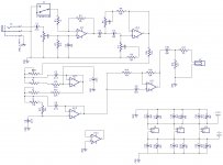
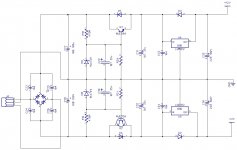
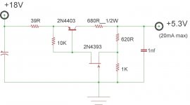
Looking at your PS , the bridge snubbers should be .01u ceramic. I've seen this
on just about all the OEM offerings - soldered directly to the bridge.
- R20-21 might be 2.2k.
- for deriving the EQ's power from the rails , it might be better to use
a higher gain device for Q2/3.
It might not be too hard to use a much better pre-regulator circuit instead
of just Q/3 + D8/9 !!
A lot of the design considerations will be of a physical nature ...
as the amp has vibration , heat and much more current to deal with on a continual basis.
I have my "slew" (amp)modified from what I would do for a full range setup.
Since this project is part preamp / amp / and speaker ,
I'm sure there are some better ideas and suggestions out there. 😀
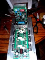
Edit - picture below of the "victim" amp , just to justify a "solid state" thread.
(biggest baddest "badger" on the forum !!)
OS
Looking at your PS , the bridge snubbers should be .01u ceramic. I've seen this
on just about all the OEM offerings - soldered directly to the bridge.
- R20-21 might be 2.2k.
- for deriving the EQ's power from the rails , it might be better to use
a higher gain device for Q2/3.
It might not be too hard to use a much better pre-regulator circuit instead
of just Q/3 + D8/9 !!
A lot of the design considerations will be of a physical nature ...
as the amp has vibration , heat and much more current to deal with on a continual basis.
I have my "slew" (amp)modified from what I would do for a full range setup.
Since this project is part preamp / amp / and speaker ,
I'm sure there are some better ideas and suggestions out there. 😀
Edit - picture below of the "victim" amp , just to justify a "solid state" thread.
(biggest baddest "badger" on the forum !!)
OS
Attachments
Last edited:
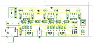
I'm thinking of modifying the design of the board a bit and and attaching an input directly to it to eliminate the connection between the boards. Less parts to fall off. The big filter caps are going to need some support. I'd like to spread 3 MT200 pairs out more and shorten the overall length too.
Would TIP122/127 be a better choice for Q2/3?
Yes , darlington multiplier ! The safety diode is built in , as well.
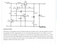
I found a better one ..... LOW COST WITH DISCRETE ELEMENTS - Circuit Diagram - TradeOfic.com
I'm going to simulate 5V ripple on it.
Only 4 discretes ... eliminates the linear regs. (has better performance , as well).
Junkbox parts !
It's feedback based , and simple.
Edit - I'm going to "scale up" the voltage using 2sa1381/ksa992-ksc1845.
OS
Attachments
Last edited:
I've got an even simpler one. Only 2 discretes!😀😀
What is it's pssr ,and can it run off 60+V ?
OS
hard at work ...
I simulated many a CFP shunt regulators , standard simple zener shunts ...
My conclusion is that it's easier to just have a separate PS for the sub EQ ,
and just use standard IC regulators.
Most OEM's use a separate full center tapped secondary on the main trafo
plus 79xx/78xx - that's all ...
1A bridge - 2200uf decoupling -star grounding for the op-amp section.
If we use a fully separate quality 10VA mini toroid , we are "one up" on
a Dayton plate amp. The slew amps are far more robust , as well.
Save the "fancy pants" feedback regulators for a preamp (some did over
100db PSRR ! 😱).
OS
I'll likely use Antek transformers in mine. They usually have extra 12V windings anyway. Do you think a cap multiplier is necessary? I'm thinking of SMT regulators for the vibration.
Maybe some extra filtering (healthy sized decoupling) for an auxiliary winding off
a main trafo.
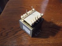
I'm using an(separate) shielded EI out of a teac tape deck. (below) E-waste is NOT waste when I get a hold of it ! 😀
2A /15-0-15vac should do.
Edit - SMD is cool - each op-amp is just 5-8ma per rail .... total EQ would just be 20-30ma/per rail.
OS
a main trafo.
I'm using an(separate) shielded EI out of a teac tape deck. (below) E-waste is NOT waste when I get a hold of it ! 😀
2A /15-0-15vac should do.
Edit - SMD is cool - each op-amp is just 5-8ma per rail .... total EQ would just be 20-30ma/per rail.
OS
Attachments
Last edited:
I remember finding a PCB mount potted toroidal that will fit the bill here perfectly. I'm just trying to remember where. I'm starting to come up with a neat design. The supply would be separate from the crossover. The crossover in a sealed billet aluminum chassis so the speaker wouldn't be blowing air out the pots.
"Deep in the motherload"
I've "dug in " to this project now.
You were right , Jeff. Lot's of "extra considerations" !! 😱
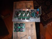
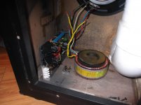
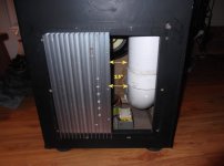
I have enough room for the PS (s) (below 1)
The plate amp (below 2) fits to the side that the port is NOT on.
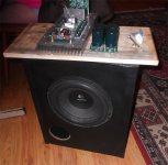
The whole "contraption" (below 3).
The stinking port takes up most of the space left over on the
(plate) side that will not have the actual amp extrusion.
I built this sub out of Albany, NY e-waste and forgot it's exact
internal layout/dimensions 😱 .
Lot's of layout decisions to consider. 🙁
OS
I've "dug in " to this project now.
You were right , Jeff. Lot's of "extra considerations" !! 😱
I have enough room for the PS (s) (below 1)
The plate amp (below 2) fits to the side that the port is NOT on.
The whole "contraption" (below 3).
The stinking port takes up most of the space left over on the
(plate) side that will not have the actual amp extrusion.
I built this sub out of Albany, NY e-waste and forgot it's exact
internal layout/dimensions 😱 .
Lot's of layout decisions to consider. 🙁
OS
Attachments
Is it possible to mount everything on the back panel of the sub? I'm hoping to mount everything on a larger aluminum heat sink in mine.
Is it possible to mount everything on the back panel of the sub? I'm hoping to mount everything on a larger aluminum heat sink in mine.
I've seen some sub amps with everything small signal
external ( a small box on the outside) .... Hey, that's a great idea - for the preamp !
The Daytons have trafo/PS/amp on the inside , and the preamp in a plastic sealed
box.
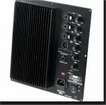
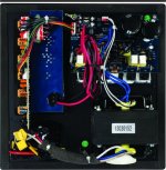
Pics below of a dayton PMA250.
Front - looks exactly like mine (will look like).
Rear - they just have things "Gooped" (caps/resistors).
Damn - mine "shames" the dayton's - even more aggressive than the PMA500 !!
Logitech always have the trafo/bridge right in the enclosure.
Edit - Yes , Jeff ..... If I did not have that monster port , I'd put the toroid and everything
on the plate. I'll have to go external for the preamp - boooohoo .
OS
Attachments
Last edited:
The crossover board is fairly small. You may be able to mount it through the back.
What are it's dimensions ?
OS
I have a full 12" X 5" on the outside of the plate where the extrusion (is not) mounted.
I nearly have just enough for the AC feed on the inside ( the port is there).
If I move the extrusion way over to the left (in my photo) I still have 2.5"
to the right of it on the inside. 2.5" X 12" is my inside layout space (now).
It's "doable" 🙂 ....
Sorry - here's the pix ...
OS
I nearly have just enough for the AC feed on the inside ( the port is there).
If I move the extrusion way over to the left (in my photo) I still have 2.5"
to the right of it on the inside. 2.5" X 12" is my inside layout space (now).
It's "doable" 🙂 ....
Sorry - here's the pix ...
OS
Attachments
Last edited:
What covers the hole in the back of the box? Is that 3/4" plywood? I can make the face plate of the crossover protrude 1/2" without looking out of place. It likely doesn't need to extend into the box much at all.
Last edited:
- Status
- Not open for further replies.
- Home
- Amplifiers
- Solid State
- Subwoofer Class AB plate amp