Hello,this thread because of my last buildin, which is the insertion of a little 4th order bandpass sub in an existing cabinet after changing old woofer with a semi-pro mid woofer.
Sub consists of a Peerless 830667, rear chamber is about 14 litres, front chamber about 16 tuned at 50 Hz through an about 7x18 cm port downward-firing against floor, 2 cm far to increase effective tube lenght.
I've choosen this loading type because of difficulty to filter any other system else through only electronic passive method.
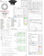
So let's came to my problem: listening it something is wrong, a vague taste of metallic closed box, so I make some measurement. Well, the truth is staggering, the reflex of sub fires a first resonance peak at about 580 Hz, and another at about 950 Hz (which I can not explain as I know should be to double the frequency of the other ..) to do horrified! Here the measurements of only sub:
1) without any filter:

2) with inserted in series to an inductance 5.6 mH:

3) since even with inductor peaks are scary I tried before to put after it a parallel 75 uF, it goes better but the impedance module has dropped close to 3 ohms, and it inflates the lowpass corner around 100 Hz, already inflated by the inductance at critical level:

4) so I do a last attempt by inserting after the inductance a LC resonant cell tuned to the first resonant peak with a rather large Q (o.82mH + 108uF), so peaks has all disappeared, but impedance module went definitively away, even in the low part of the response, and this to me is incomprehensible:

What a disaster! Let's go to the conclusions, it remains only one way: may the reflex tube be replaced by a passive radiator? The latter should not be affected by the problem of the secondary resonance peaks, or not?
Seeking a moment, there are two alternatives, the Dayton 10-inch with minimum moving mass of 100 grams or the SEAS 8 inches with minimum moving mass of 28 grams. Pros and cons of each: the Dayton has a mass such that the resultant Fb should be from about 45 HZ down, while the Seas has such a that the value of 50 Hz, that for me must be more or less a mean value is precisely average of its possibilities, only the Seas costs twice of Dayton and is an 8-inch instead of 10.
In short, I am quite confused and did not know whether to continue spending in this experiment or not. Any advice, especially for confirmation that with passive solve the secondary resonances?
Thank you very much.
Sub consists of a Peerless 830667, rear chamber is about 14 litres, front chamber about 16 tuned at 50 Hz through an about 7x18 cm port downward-firing against floor, 2 cm far to increase effective tube lenght.
I've choosen this loading type because of difficulty to filter any other system else through only electronic passive method.
So let's came to my problem: listening it something is wrong, a vague taste of metallic closed box, so I make some measurement. Well, the truth is staggering, the reflex of sub fires a first resonance peak at about 580 Hz, and another at about 950 Hz (which I can not explain as I know should be to double the frequency of the other ..) to do horrified! Here the measurements of only sub:
1) without any filter:
2) with inserted in series to an inductance 5.6 mH:
3) since even with inductor peaks are scary I tried before to put after it a parallel 75 uF, it goes better but the impedance module has dropped close to 3 ohms, and it inflates the lowpass corner around 100 Hz, already inflated by the inductance at critical level:
4) so I do a last attempt by inserting after the inductance a LC resonant cell tuned to the first resonant peak with a rather large Q (o.82mH + 108uF), so peaks has all disappeared, but impedance module went definitively away, even in the low part of the response, and this to me is incomprehensible:
What a disaster! Let's go to the conclusions, it remains only one way: may the reflex tube be replaced by a passive radiator? The latter should not be affected by the problem of the secondary resonance peaks, or not?
Seeking a moment, there are two alternatives, the Dayton 10-inch with minimum moving mass of 100 grams or the SEAS 8 inches with minimum moving mass of 28 grams. Pros and cons of each: the Dayton has a mass such that the resultant Fb should be from about 45 HZ down, while the Seas has such a that the value of 50 Hz, that for me must be more or less a mean value is precisely average of its possibilities, only the Seas costs twice of Dayton and is an 8-inch instead of 10.
In short, I am quite confused and did not know whether to continue spending in this experiment or not. Any advice, especially for confirmation that with passive solve the secondary resonances?
Thank you very much.
Last edited:
...may the reflex tube be replaced by a passive radiator? Any advice, especially for confirmation that with passive solve the secondary resonances?
A passive won't have pipe resonances, but may have cone resonances.
A rule of thumb is that the passive should have roughly 2x the excursion volume as the woofer. Be sure to simulate excursion with your selected passives.
Since you have measurement capability, try a little damping material on the walls of the vented portion.
I have tried it and it works well. The efficiency might however be lower, as some passives have high losses. I used the Dayton SD215-PR which has a paper cone.
A passive won't have pipe resonances, but may have cone resonances.
A rule of thumb is that the passive should have roughly 2x the excursion volume as the woofer.
Ok, excursion will never be a problem for my system and for my kind of use, but l eme understand better about cone resonances, is there a way to discover them at project level? Are them related to cone excursion? Thanks.
Thank you very much, I too would use the Dayton 215 but its highest tuning frequqncy is too low for my application, so it would be better the 270 (which fits for some millimeters in the lateral side of cabinet..).I have tried it and it works well. The efficiency might however be lower, as some passives have high losses. I used the Dayton SD215-PR which has a paper cone.
At purpose, in what side it would better positioning PR, in that facing or in the opposites in your opinion?
Since you have measurement capability, try a little damping material on the walls of the vented portion.
This. Damping material will make a difference. See The Subwoofer DIY Page v1.1 - Projects : An INF10 Bandpass Subwoofer for my own experiments and measurements.
I'd even try going for filling the entire vented section with polyester fiberfill, then resizing the vents (make them shorter) to retune the enclosure back to the target resonance frequency.
Thank you, my compliments for your building! I'll do all trials filling up vented chamber. It may seem strange but in Italy I'm in difficult in finding polyester fiber fill. Alternatively what do you think about lamb wool filling, as:This. Damping material will make a difference. See The Subwoofer DIY Page v1.1 - Projects : An INF10 Bandpass Subwoofer for my own experiments and measurements.
 ?
?In reality I haven't yet a real measurement microphone, I just used a borrowed panoramic mic with a Monacor MPA102 of mine and the onboard audio card.. Certainly my purpose is only relative comparations between different steps: this raw method has been really really useful and without it I would be still in vain walking!Since you have measurement capability, try a little damping material on the walls of the vented portion.
Thank you.
Natural fibers are fine, but insect pests such as carpet beetles or wool moths like to eat it. Polyester fiber fill such as pillow stuffing or quilt batting is available in sewing/craft shops. You can even buy cheap pillows and use that. If it works to your liking, then go for the "boutique" stuff.
Another possible source of resonance is the port tube itself if it has thin walls. You could add some damping material such as modeling clay or an old mouse pad affixed with string, etc... so that it sounds more dead when you flick it with a finger.
Another possible source of resonance is the port tube itself if it has thin walls. You could add some damping material such as modeling clay or an old mouse pad affixed with string, etc... so that it sounds more dead when you flick it with a finger.
Hi Bjiorno, thanks thanks! But I must say that I've said badly port dimensions, I'm really sorry for the confusion, with "7x18" I intended 7 cm diameter and 18 cm lenght.. excuse me!
However, I'd want to understand better: if the grey hatch in the filled simulation is polyfill, is there filling in the vent? Thank you and excuse me again..🙄
However, I'd want to understand better: if the grey hatch in the filled simulation is polyfill, is there filling in the vent? Thank you and excuse me again..🙄
..and thank you to Ron E toofor the useful information, even about the damping of the vent, I have just some old mouse pad to bring back to life..
Another possible source of resonance is the port tube itself if it has thin walls. You could add some damping material such as modeling clay or an old mouse pad affixed with string, etc... so that it sounds more dead when you flick it with a finger.
A little bit of flashing tape should accomplish the same thing.
I'll bet the primary resonances are due to box and vent dimensions however. Stuffing should significantly reduce that, but the vent may have to be trimmed to compensate for the downward shift in Fb.
Sonus Faber dampen their ports (that sounds rude) ... they call it Stealth Reflex
An externally hosted image should be here but it was not working when we last tested it.
An externally hosted image should be here but it was not working when we last tested it.
Last edited:
Hi Bjiorno, thanks thanks! But I must say that I've said badly port dimensions, I'm really sorry for the confusion, with "7x18" I intended 7 cm diameter and 18 cm lenght.. excuse me!
However, I'd want to understand better: if the grey hatch in the filled simulation is polyfill, is there filling in the vent? Thank you and excuse me again..🙄
Hi andreaemme,
If the port dimensions is 7 cm in diameter and of 18 cm length: Maximum Input Power would be ~8W before severe Port issues.
Yes the Gray Hatched Area is Stuffing where the Flow Resistance is important
not the eventually Sound Absorption that can vary depending on the Material in use.
b🙂
Thank you! Unfortunately any other lenght won't fit in my little chamber but power won't be a concern because I ratherly I go above these numbers..
Have a good time!
Have a good time!
- Status
- Not open for further replies.
- Home
- Loudspeakers
- Subwoofers
- Substituting vent with passive radiator in a 4th order bandpass