Try a lower setting, go down to 200mV if you have it, although if it's only a few mV then that's not likely to kill an amp, but as I said with the DC blocking cap it should be substantially zero so it's worth making sure that you don't have a bad component in there.
The 1M thing, like with so many electric guitar related stuff, is kind of a de facto standard, something that stuck from the way amplifiers were built way back when. In fact you can find amps with anything from 220k to 2.2M, whatever the designer thought was appropriate as a grid load resistor for the first tube in the input stage, but 1M is the most common value and what is usually used as input impedance for pedals too.
Cheers,
Cabirio
Try a lower setting, go down to 200mV if you have it, although if it's only a few mV then that's not likely to kill an amp, but as I said with the DC blocking cap it should be substantially zero so it's worth making sure that you don't have a bad component in there.
The 1M thing, like with so many electric guitar related stuff, is kind of a de facto standard, something that stuck from the way amplifiers were built way back when. In fact you can find amps with anything from 220k to 2.2M, whatever the designer thought was appropriate as a grid load resistor for the first tube in the input stage, but 1M is the most common value and what is usually used as input impedance for pedals too.
Cheers,
Cabirio
Interesting. I wonder why this one was built with such a comparatively low impedance/resistance. So, 1Meg generally keeps the resonant frequency of all other pickups before the roll off? Except for Gretsch Filtertrons? (that are about 4k if I recall correctly) that can get by withc as low as 56k?
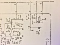
Here's a section of the drawing just below the op amp. I guess this is a clear indication that -/+14V is the supply for the opamps. I have it at -/+9V now. I have a few 10V supplies here that actually output 14V. Perhaps I should try them to see if the performance of the chip changes with the voltage at spec.
Attachments
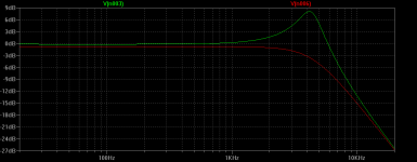
Well, it's interesting actually. With such low resistance you can expect also correspondingly lower inductance and capacitance. If they are 4k, half of a typical PAF, we can guesstimate also half L and C: see below what you get with those values and 1M and 56k loading. With 1M the peak is huge and at a higher frequency, 4kHz or so (ouch!), not even single coils give that kind of response. With 56k the peak is gone but the FR remains flat also until much higher up than in the PAF example. You could go with something intermediate to lower the peak but keep some of it and with it the characteristic pickup sound, so making the resistor variable may be good to fine-tune it by ear, though as I said you will get pretty much the same effect by lowering the tone control in the guitar.
I doubt you will hear much of a difference between +/-9 and +/-14V, but you seem keen on keeping the circuit to original specs, so no harm in giving it a try.
Cheers,
Cabirio
I doubt you will hear much of a difference between +/-9 and +/-14V, but you seem keen on keeping the circuit to original specs, so no harm in giving it a try.
Cheers,
Cabirio
Attachments
That's very interesting. I wonder if a variable resistance could be used to push the resonant frequency back and get it to line up with the typical range where that sitar-like phenomenon that occurs with Gretsches with seeming unpredictability. I realize that statement is a bit vague, lol. But with your estimated numbers for a filtertron, the peak goes from negligibly far off the scale to the right and then moves inward to the usable spectrum to find itself at 4k? Would more resistance push it even lower?
If someone wanted to simulate 30' of long guitar cord capacitance, let's say 3.3nF, would said capacitance simply be placed in series with the incoming signal?
If someone wanted to simulate 30' of long guitar cord capacitance, let's say 3.3nF, would said capacitance simply be placed in series with the incoming signal?
Last edited:
I tried putting a 1Meg pot in series with the 56k (R223) to ground and it did absolutely nothing. I had my wife vary it while i played the Gretsch and I could not detect the slightest bit of change. This was already a pretty bright sounding scenario so i expected something. R223 is the one you meant, right?
Maybe I didn't explain myself: the trace with the peak is the one with 1M load, lowering the resistance is what flattens it, but it doesn't affect its frequency. That depends on the capacitance, so if you want to move it down in frequency, then yes, you can add a cap, but in parallel with the input, not in series.That's very interesting. I wonder if a variable resistance could be used to push the resonant frequency back and get it to line up with the typical range where that sitar-like phenomenon that occurs with Gretsches with seeming unpredictability. I realize that statement is a bit vague, lol. But with your estimated numbers for a filtertron, the peak goes from negligibly far off the scale to the right and then moves inward to the usable spectrum to find itself at 4k? Would more resistance push it even lower?
If someone wanted to simulate 30' of long guitar cord capacitance, let's say 3.3nF, would said capacitance simply be placed in series with the incoming signal?
Yes, it's R223. You wouldn't happen to be in the -50dB gain mode when you did the test? Because that puts R217 / 3K3 between input and ground and that will pretty much swamp the effect of R223 + the pot. As I said somewhere above you can just remove R217, it's there to lower even more the input impedance for microphone use and you don't need it. In fact it will also reduce the gain in that setting because with it you have a significant voltage divider with the pickup resistance. If you weren't using that gain setting, then I don't really know why you didn't hear a difference, it should be pretty obvious...I tried putting a 1Meg pot in series with the 56k (R223) to ground and it did absolutely nothing. I had my wife vary it while i played the Gretsch and I could not detect the slightest bit of change. This was already a pretty bright sounding scenario so i expected something. R223 is the one you meant, right?
So I rebuilt the circuit on a breadboard so I can tweak things without opening up my precarious pedal box. I excluded all the additional circuitry pertaining to the -50dB and -20dB setting. I retried the 1Meg resistance in series to ground after the 56k and although the unshielded nature of the breadboard along with an increase of resistance to the ground made more RF noise as I turned the knob, the frequency response of the guitar remained the same. I wonder if this is because of the impedance, etc of the guitar and perhaps the response would be different if I plugged in a Strat?
Also, I check the DC offset down 200mV on the multimeter, cranked volume, shorted input (that part is to ensure no AC component, I presume?) and on the -20dB setting.
Also, I check the DC offset down 200mV on the multimeter, cranked volume, shorted input (that part is to ensure no AC component, I presume?) and on the -20dB setting.
Another thing I am wondering about: Is there a general area where less "tone shaping" efforts are placed in an op amp circuit? For instance, are all such components occurring as high/low/band pass filters on the non-inverting input to the op amp?
Hang on: you wouldn't happen to have the other pedal connected between the guitar and the booster?I retried the 1Meg resistance in series to ground after the 56k and although the unshielded nature of the breadboard along with an increase of resistance to the ground made more RF noise as I turned the knob, the frequency response of the guitar remained the same.
Hang on: you wouldn't happen to have the other pedal connected between the guitar and the booster?
No, just the booster.
I'm sorry Bouquin but I'm out of ideas. Whether it's a Filtertron, a Strat or any other passive pickup, putting 56k to ground is roughly equivalent to turning a 500k tone pot down to 5, the difference should be obvious. All I can suggest is that you draw a detailed schematic of exactly what you have now and I'll take another look...
I'm sorry Bouquin but I'm out of ideas. Whether it's a Filtertron, a Strat or any other passive pickup, putting 56k to ground is roughly equivalent to turning a 500k tone pot down to 5, the difference should be obvious. All I can suggest is that you draw a detailed schematic of exactly what you have now and I'll take another look...
No problem. You have been such a great help already and I appreciate it! For the moment, it's a non issue till I try the circuit on something that isn't a Gretsch. I'm putting this concern off till later.
I'm sorry Bouquin but I'm out of ideas. Whether it's a Filtertron, a Strat or any other passive pickup, putting 56k to ground is roughly equivalent to turning a 500k tone pot down to 5, the difference should be obvious. All I can suggest is that you draw a detailed schematic of exactly what you have now and I'll take another look...
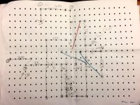
Update: So I brought the pedal over to my dad's place and tried it on his Princeton with a Telecaster. And still, no treble issues despite the low input impedance. I have read reports about the echo machine from which the preamp originates suffering from impedance mismatch and the manual states it is indeed a 56k input impedance. Nonetheless, I cannot detect any loss of treble nor can I deduce any change in treble response be varying the 1Meg pot in series with the 56k resistor. I am almost certain it does absolutely nothing. So, I am posting my layout as you suggested in case there is something blatantly amiss. Incidentally, the pre-amp sounds pretty good...
Attachments
So, I went back to the drawing board and cranked the op amp up to full on a very low master volume one the guitar amp. I put the guitar on the bridge pickup and cranked the 1M pot back and forth .... you were right, I can hear a treble difference, now. It is subtle but not too subtle that it might not be there. I can even hear it affecting the ambient noise on the guitar. I suspect it would be more exaggerated on a high output impedance guitar. Sorry to have doubted you! 😀
No offense taken, you'd be crazy not to doubt what some random guy tells you in a forum!  I'm glad it worked out in the end, and btw I don't know how you have the pots in the guitar set up but you will hear the biggest change with both the tone and volume fully open, otherwise their effect will dominate and the input impedance of the pedal won't make that much of a difference.
Cheers,
Cabirio
I'm glad it worked out in the end, and btw I don't know how you have the pots in the guitar set up but you will hear the biggest change with both the tone and volume fully open, otherwise their effect will dominate and the input impedance of the pedal won't make that much of a difference.Cheers,
Cabirio
Hi again!
Remember when this thread recommended that I replace the 56k resistor with a 1M ohm on the input to the op amp in question to avoid treble loss from impedance mismatch when the op amp is the first pedal in the signal chain? I have been doing this successfully and switching it on and off. However, I get true bypass switch pops only when the impedance is at 1M and not when it's at 56k. I have tested a few things including a nearby LED but that was not the problem. Any thoughts on what's going on here?
Thanks!
I'm not sure where you are up to in all this but this might give you a clue...
Pops occur when the audio is suddenly shifted about some voltage, so if your bypass switch connects between two points of differing voltage (even if its AC coupled with a cap) then you will get a pop.
Pops occur when the audio is suddenly shifted about some voltage, so if your bypass switch connects between two points of differing voltage (even if its AC coupled with a cap) then you will get a pop.
- Status
- Not open for further replies.
- Home
- Source & Line
- Analog Line Level
- Substituting Toshiba Op-Amp Into Circuit