While I was waiting I rolled the dice and tried it and it worked. But the power supply does say "isolated DC outputs" right on the top of the unit. It's one of those popular Voodoo Labs affairs. But now, thanks to you, I know the circuit works. Thanks so much! Now I can do the virtual ground thing instead the convoluted set-up. I wonder what I should to get +/-14V. Maybe a 36V supply and step it down with a resistor to 28V? I mean if I was trying to be 100% authentic and conserve the original voltage.
Dear Bouquin, (vous habitez a la rive gauche du Seine? 😉 ) , I see a couple problems with your pedal project 🙁
1) the main one: you speak of a clean preamp, but running it from 9V total instead of 28V total (14+14) will severely restrict clean signal handling.
It's even worse than it looks, because regular Op Amps can't swing too close, often not less than 3 v from one, 2 V from the other, so consider 9V as if you only had (usable) 4 or 5V.
Your preamp will work fine as tested, when fed from bench supplies, but fall short when only a 9V battery (or a typical pedal supply) is used.
2) and you still need to convert it to single 9V
3) I recognize the preamp , it's a typical 70's , early 80's Japanese mixer input channel, among others Roland, Ibanez and Yamaha , with its classic 3 way toggle switch, varying first stage gain to adjust it to Mic/Instrument/Line levels.
In the Mic position (-50dB) it also pads input impedance down.
Very dated, no special magic there, there's simpler and better today.
What will you actually plug there?
Which setting will you use?
4) neither the Op Amp is magic, only special feature is that it was Low Noise ... for 70's standards and in that respect way better than 741; but you can use , say, a TL071 there, same pinout as 741 , and get less noise, wider bandwidth and probably less distortion.
And with values shown, it will be stable.
5) IF you want a good clean preamp, designed for 9v , check the MXR MicroAmp .
For an analysis which you will find useful:
ElectroSmash - MXR MicroAmp Analysis.
note: on the schematic there's a number "1" drawn closem to the output; don't know why it's there, because pinout is same as 741 so output is pin 6 on the DIP8 version.
Dear Bouquin, (vous habitez a la rive gauche du Seine? 😉 ) , I see a couple problems with your pedal project 🙁
1) the main one: you speak of a clean preamp, but running it from 9V total instead of 28V total (14+14) will severely restrict clean signal handling.
It's even worse than it looks, because regular Op Amps can't swing too close, often not less than 3 v from one, 2 V from the other, so consider 9V as if you only had (usable) 4 or 5V.
Your preamp will work fine as tested, when fed from bench supplies, but fall short when only a 9V battery (or a typical pedal supply) is used.
2) and you still need to convert it to single 9V
3) I recognize the preamp , it's a typical 70's , early 80's Japanese mixer input channel, among others Roland, Ibanez and Yamaha , with its classic 3 way toggle switch, varying first stage gain to adjust it to Mic/Instrument/Line levels.
In the Mic position (-50dB) it also pads input impedance down.
Very dated, no special magic there, there's simpler and better today.
What will you actually plug there?
Which setting will you use?
4) neither the Op Amp is magic, only special feature is that it was Low Noise ... for 70's standards and in that respect way better than 741; but you can use , say, a TL071 there, same pinout as 741 , and get less noise, wider bandwidth and probably less distortion.
And with values shown, it will be stable.
5) IF you want a good clean preamp, designed for 9v , check the MXR MicroAmp .
For an analysis which you will find useful:
ElectroSmash - MXR MicroAmp Analysis.
note: on the schematic there's a number "1" drawn closem to the output; don't know why it's there, because pinout is same as 741 so output is pin 6 on the DIP8 version.
😀 Thanks! Yes, I realize it is old and outdated. There's nothing terribly special about it either. I guess I wanted to see if I could revive the original to exact spec.
How do you think I might power it with a single AC adapter? I would need to make a virtual ground with a 28V source, right?
Don't get too hang up on the exact voltage, and since you have a nice Voodoo supply with isolated outputs, you can indeed use two of them in series with a proper middle point / ground. Or, if you don't want the complication, use the 18V output (you said you had one, right?) with the voltage divider. That will give you more headroom which is always good as JMFahey said, especially with a clean booster. I've built some powered at 9V for convenience and if you put them after say a Tubescreamer with the output set high, the booster will clip and no longer be clean. +1 on getting a better opamp, how about an AD820 that has a rail-to-rail output and will use the full supply voltage.
In fact you could even have that problem with the MXR MicroAmp mentioned by JMFahey (which is the example I gave in post #18), it runs on 9V and uses a TL061 that typically will swing 1.5V below the rails, so feed it a hot signal, turn it up and say bye-bye to clean. Watch out for the reverse problem too: if you put the booster before a 9V pedal and crank it up, it will saturate its input, which may or may not be what you want. And the same goes for your amp's input: be careful or you may well turn your clean channel into a crunchy one. So I'd think twice before going above 18V, that's already plenty for the levels you're dealing with. In the end it all depends on your chain and what you want to do, you will have to go through some trial and error to set your levels right and get the result you want. Here's a tip: I've found that it helps to think of the booster more as an attenuator. See how much difference you want between boosted and not, engage it, adjust other pedals and amp like that and when you switch it off, you're guaranteed not to have any problems with things distorting that you don't want to. As a last resort, you can always put the booster in your effects loop (if you have one) which usually takes much higher levels before clipping.
Cheers,
Cabirio
Don't get too hang up on the exact voltage....
Cheers,
Cabirio
Yeah, running two of the 9V isolated sources from the Voodoo Lab is no big deal. I'm perfectly okay with it. However, when I had that chip in the pedal circuit posted online which was set up for 0-9V (as opposed to this echo machine preamp circuit) there was an audible difference if I ran it up at 18V instead of 9V. It seemed to have more high end. Too bad this pedal power unit doesn't have two 18V outputs. I'm not super concerned about clipping from pedals upstream of the chain. All I use is an EL Capistan before this boost and I guess I am interested in the coloring of the signal by virtue of this chip and it's surrounding components as they were originally.
Disaster has struck. The preamp has 3 settings in addition to a volume knob. -20dB, -35dB and -50dB. I was testing the circuit which was working fine and i turned it up too high while in the -20dB setting and took out my little Gretsch g5222 amp AND the opamp... Well, at least I know the circuit works... ugh...
Any thoughts on what happened inside the small guitar amp? It smell all electrical/burnt... I looked at the board and nothing looks obviously burnt...
Any thoughts on what happened inside the small guitar amp? It smell all electrical/burnt... I looked at the board and nothing looks obviously burnt...
Sorry to hear about the amp.
I'm confused as to what you are running here, and so I'm assuming the opamp and preamp are a separate item to the guitar amp. Google tells me the Gretsch g5222 is actually a small valve amp. Electrical burn smell could even be one of the transformers, either the mains tranny or the output tranny.
I'm confused as to what you are running here, and so I'm assuming the opamp and preamp are a separate item to the guitar amp. Google tells me the Gretsch g5222 is actually a small valve amp. Electrical burn smell could even be one of the transformers, either the mains tranny or the output tranny.
Sorry to hear about the amp.
I'm confused as to what you are running here, and so I'm assuming the opamp and preamp are a separate item to the guitar amp. Google tells me the Gretsch g5222 is actually a small valve amp. Electrical burn smell could even be one of the transformers, either the mains tranny or the output tranny.
Sorry for the confusion. The opamp and the "original" circuit I have been referencing *IS* the preamp. The original circuit has a 3 way switch and a volume knob. It switches between -20, -35 and -50dB. I put it one -20 and turned the volume way up even though there was not much guitar signal coming through and the Gretsch amp was at a low setting the signal damaged something in the Gretsch and presumably fried the opamp as well.
OK. Hard to see how the opamp could get fried by the other amp as both will be AC coupled. Something odd must have occurred if it really has damaged the opamp.
Well, I found a local stash of the TA7136P s and bought a few. I put a new one in the circuit and I'm back in business. I also found a used Gretsch amp so replace mine that is out of commission for unknown reasons. Note to self: don't use the -20dB setting. In the manual for the echo machine, it says the -50dB is for mics, -35dB is for guitars and -20dB is for synthesizers.
If what caused the problem was too hot a signal, it doesn't make sense that the culprit is the lowest gain setting. Looking at the schematic the only thing I can imagine going wrong is the output DC blocking cap (C115) being very leaky or shorted and letting a large DC offset go through. I would measure that just to be sure and replace it if necessary. This is consistent with "there was not much guitar signal coming through" and turning up the volume, which would have put that full DC offset at the input of the amp.
While you're at it you may also want to replace R223 with a 1Meg resistor. That sets the input impedance (in low and mid gain settings, in high it's R217 - 3k3, you can just remove it) and while the El Capistan may be happy with 56k, if you ever connect the guitar directly to the booster and/or the El Capistan is true bypass, your pickups will want to see about 1Meg to give the right sound, otherwise such a low impedance will kill the resonant peak before roll-off and give a muffled, dark sound.
Cheers,
Cabirio
If what caused the problem was too hot a signal, it doesn't make sense that the culprit is the lowest gain setting. Looking at the schematic the only thing I can imagine going wrong is the output DC blocking cap (C115) being very leaky or shorted and letting a large DC offset go through. I would measure that just to be sure and replace it if necessary. This is consistent with "there was not much guitar signal coming through" and turning up the volume, which would have put that full DC offset at the input of the amp.
While you're at it you may also want to replace R223 with a 1Meg resistor. That sets the input impedance (in low and mid gain settings, in high it's R217 - 3k3, you can just remove it) and while the El Capistan may be happy with 56k, if you ever connect the guitar directly to the booster and/or the El Capistan is true bypass, your pickups will want to see about 1Meg to give the right sound, otherwise such a low impedance will kill the resonant peak before roll-off and give a muffled, dark sound.
Cheers,
Cabirio
That's very interesting. There's some suggestion that this deivce works well with Gretsches because of the relatively low impedance of Filtertron pickups. Can you elaborate on that impedance mismatch phenomenon? I saw R223 and a capacitor going to ground and assumed it was a pass filter to exclude certain frequencies.
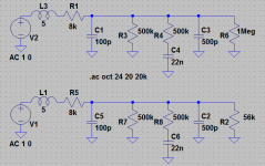
The sound of a guitar / bass pickup is the result of (typical values in brackets):
- The pickup's inductance, resistance and parasitic capacitance (for a typical PAF type humbucker, 5H, 8k, 100pF)
- The volume and tone control circuit (let's say 500k vol. and tone pots and 22nF tone cap, again typical for humbucker-equipped guitars)
- The cable capacitance (500pF for 5m of a 100pF/m cable)
- The amplifier input impedance (1M resistance + some capacitance, but the cable capacitance dominates)
This gives you a low pass response with a resonant peak before roll-off, the frequency and amplitude of which determines the "voice" of the pickup (*). For example single coils usually have the peak higher in frequency than humbuckers, hot humbuckers lower in amplitude than low output ones, etc.
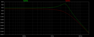
I've simulated the above circuit in LTSpice and then replaced the 1M with the 56k of your circuit (see below. Note that the parasitic capacitance is actually distributed, but the lumped model seems to work ok). As you can see the lower impedance kills completely the resonant peak. With a trebly pu like a Filtertron this may work well, but I'd rather use the tone control to adjust this than never be able to get that jangly, bright sound if I need it.
Cheers,
Cabirio
(*) as well as the position of the pickup with respect to the strings and the phase cancellation between coils in a humbucker or a combination of two single coils (the famous Strat "quack"). This app shows these effects and is a lot of fun!
- The pickup's inductance, resistance and parasitic capacitance (for a typical PAF type humbucker, 5H, 8k, 100pF)
- The volume and tone control circuit (let's say 500k vol. and tone pots and 22nF tone cap, again typical for humbucker-equipped guitars)
- The cable capacitance (500pF for 5m of a 100pF/m cable)
- The amplifier input impedance (1M resistance + some capacitance, but the cable capacitance dominates)
This gives you a low pass response with a resonant peak before roll-off, the frequency and amplitude of which determines the "voice" of the pickup (*). For example single coils usually have the peak higher in frequency than humbuckers, hot humbuckers lower in amplitude than low output ones, etc.
I've simulated the above circuit in LTSpice and then replaced the 1M with the 56k of your circuit (see below. Note that the parasitic capacitance is actually distributed, but the lumped model seems to work ok). As you can see the lower impedance kills completely the resonant peak. With a trebly pu like a Filtertron this may work well, but I'd rather use the tone control to adjust this than never be able to get that jangly, bright sound if I need it.
Cheers,
Cabirio
(*) as well as the position of the pickup with respect to the strings and the phase cancellation between coils in a humbucker or a combination of two single coils (the famous Strat "quack"). This app shows these effects and is a lot of fun!
Attachments
The sound of a guitar / bass pickup is the result of (typical values in brackets):
- The pickup's inductance, resistance and parasitic capacitance (for a typical PAF type humbucker, 5H, 8k, 100pF)
- The volume and tone control circuit (let's say 500k vol. and tone pots and 22nF tone cap, again typical for humbucker-equipped guitars)
- The cable capacitance (500pF for 5m of a 100pF/m cable)
- The amplifier input impedance (1M resistance + some capacitance, but the cable capacitance dominates)
This gives you a low pass response with a resonant peak before roll-off, the frequency and amplitude of which determines the "voice" of the pickup (*). For example single coils usually have the peak higher in frequency than humbuckers, hot humbuckers lower in amplitude than low output ones, etc.
I've simulated the above circuit in LTSpice and then replaced the 1M with the 56k of your circuit (see below. Note that the parasitic capacitance is actually distributed, but the lumped model seems to work ok). As you can see the lower impedance kills completely the resonant peak. With a trebly pu like a Filtertron this may work well, but I'd rather use the tone control to adjust this than never be able to get that jangly, bright sound if I need it.
Cheers,
Cabirio
(*) as well as the position of the pickup with respect to the strings and the phase cancellation between coils in a humbucker or a combination of two single coils (the famous Strat "quack"). This app shows these effects and is a lot of fun!
Wow, you guys are so well-versed in this stuff. Thanks! WOuld you say it would be feasible to put that 56k as a variable resistance to accommodate other guitars yet retain the ability to bring the circuit back to stock?
Sure, that would work. You could put a 1M pot in series with the 56k resistor, that way you can go from "stock" at 0 to "standard impedance" at max. I'd use a log pot connecting the wiper to the input line, the bottom to the 56k resistor and that one to ground.
Did you check if you had some DC offset at the output? I'm still intrigued as to what happend to the poor little Gretsch...
Did you check if you had some DC offset at the output? I'm still intrigued as to what happend to the poor little Gretsch...
Sure, that would work. You could put a 1M pot in series with the 56k resistor, that way you can go from "stock" at 0 to "standard impedance" at max. I'd use a log pot connecting the wiper to the input line, the bottom to the 56k resistor and that one to ground.
Did you check if you had some DC offset at the output? I'm still intrigued as to what happend to the poor little Gretsch...
I have not checked that yet. Do I need an oscilloscope or could i simply put my multimeter in DC and see if I get a non-zero value at the output?
Yup: short the input, leave the output open and measure it with the volume at max. If you get some DC offset, C115 is faulty and you need to replace it.
Yup: short the input, leave the output open and measure it with the volume at max. If you get some DC offset, C115 is faulty and you need to replace it.
There does not seem to be any measurable DC component. I had the meter at 20V so if there is anything there it is beneath the resolution of that mode. You may still be right, though, because I forgot that I had built the board up from scratch again after the amp burnout.
Why is 1Mohm a "standard" input impedance? Are all pedals set up that way?
- Status
- Not open for further replies.
- Home
- Source & Line
- Analog Line Level
- Substituting Toshiba Op-Amp Into Circuit