Hi, everyone! I'm a new member!
I have a guitar effects pedal that I built based on an online design. It is essentially a "clean boost" and is based around an LM741 op amp. My background is mechanical eng so my electronics are not super strong, but I assumed that if the circuit already worked fine with one opamp, substituting another while accounting for any pinout differences would result in a successful transplant. As far as I can tell, the Toshiba TA7136P that I want to use has the 2 and 3 pin inverted relative to the LM741 i.e. inverting and non-inverting input are reversed. Otherwise, the pins are the same (the existing circuit makes no use of pins of 1 and 5)
I wired in a new-old-stock Toshiba TA7136P and the circuit behaves like there is no power going to it. In other words, the signal still finds it's way to the amp without gain but still responds to "gain" knob in that turning it down makes it quieter. But this is exactly how the circuit behaved with the LM741 if I left it unpowered in the signal chain. The only thing that does occur is a pop that runs through the signal path when I apply power.
My practical knowledge of op amps is limited so I am not sure if perhaps
1) pin 1 and 5 need special attention on older op amps used as signal amplifiers?
2) chip is a dud?
Any thoughts or suggestions are appreciated!
Thanks!
I think pin 5 needs to be connected via a resistor (resistor value depends on supply voltage) to the positive rail. Pin 5 is a bias pin for the constant current sink within the chip.
I think pin 5 needs to be connected via a resistor (resistor value depends on supply voltage) to the positive rail. Pin 5 is a bias pin for the constant current sink within the chip.
Thanks, Mooly! This is a 9V scenario. How would one go about sizing the resistor? And by "positive rail" you mean the +power supply to the opamp i.e. pin 7?
Do you mean a single 9 volt battery ? You might the find TA7136P won't operate very well at such a low supply. Its an ancient device that was around before the industry standard 741 and all its later derivatives appeared. By all means try it but just be aware...
I would guess at something like 6k8 or 8k2 which would allow around 1ma to flow... about right for what it has to do.
If your just after improving on the 741 then there are many other more suitable devices, and if battery operated then devices with much lower power consumption too.
And yes... to the positive pin.
A bit more info looking at typical applications of the TA7136P. You might find it unstable (oscillates at high frequency) without you adding an external frequency compensation capacitor between pin 1 and 6. This is where you really need an oscilloscope to see how it all behaves but at a guess a 47pf cap would be in the right ball park.
Thanks again! I am running a "Pedal Power" supply that has outputs for odd pedals at 12V and 18V in addition to the standard 9V. I guess I could try the 18V since the spec sheet indicates the Toshiba can handle up to 22V. In which case, I should use around 16k resistor if I run 18V.
I'll try that and then see if it works then listen for the oscillations.
I'll try that and then see if it works then listen for the oscillations.
This is what happens when opamps oscillate,
http://www.diyaudio.com/forums/anal...u-have-checked-see-its-stable-havent-you.html
I would definitely run chip on the higher supply voltage if possible. The resistor isn't critical, it just has to supply enough current to fully saturate an internal transistor in the chip without forcing to much current into the pin. Anything between say 1 and 5 ma should be fine.
From that very informative post I have gleaned that oscillations may not be audible but they could interfere with the audible spectrum of the opamp and give an incorrect impression of its performance, correct?
Yes, if the oscillation is above the audio band (which it nearly always is) then it affects the perceived sound in unpredictable ways.
It works, now! However, there is a lot of radio interference coming through. Even when the the metal box, which is well ground on top and bottom, is closed. With the LM741 there was no RF interference once I grounded the circuit to the interior of the box. I wonder if it might be oscillating as you suggested and that is somehow exaggerating the ambient RF noise?
Also, changing the gain setting seems to "tune in" other frequencies. Some are not even radio frequency but just background squeals that are slowly increasing in pitch.
Yes, its very likely it is oscillating.
This is where you need a scope to see what is going on and to look at how the circuit might be changed to get a device like this to work correctly. There's no other way to do it I'm afraid.
A lot of older chips like this, although drawn as conventional opamps don't always quite behave as we expect.
This is where you need a scope to see what is going on and to look at how the circuit might be changed to get a device like this to work correctly. There's no other way to do it I'm afraid.
A lot of older chips like this, although drawn as conventional opamps don't always quite behave as we expect.
Thanks so much for your help! I guess I shouldn't be surprised to find such precise answers to such specialized questions. But it's fun when the miracle of the "innernet" catches you off guard.
Now that I know the opamp works, I'm going to wire it into a known circuit that uses it for preamplification of a guitar signal. Already I can see artifacts in the circuit that correspond to the issues you mentioned... a 22pF going from 6 to 1.... a 100k resistor running from 5 to the power supply....
Now that I know the opamp works, I'm going to wire it into a known circuit that uses it for preamplification of a guitar signal. Already I can see artifacts in the circuit that correspond to the issues you mentioned... a 22pF going from 6 to 1.... a 100k resistor running from 5 to the power supply....
Update: I wired the opamp into the original circuit and I got nothing. I turn the "volume" knob up (not really a variable gain I don't think in this case) and I get hiss so I think it's "on" but not getting the signal.
I've trouble-shot and checked the connections and I *think* i have it right except I recently noticed that the circuit appears to be set up for two power supply operation. Pin 7 is an upward arrow labeled +14V elsewhere in the complete device drawing and Pin 4 is -14V indicated by a downward arrow. But I have 4 connected straight to ground. What sort of effect would this have? I can temporarily wire a -9V to accompany the +9V I have going into Pin 7 to verify.
I've trouble-shot and checked the connections and I *think* i have it right except I recently noticed that the circuit appears to be set up for two power supply operation. Pin 7 is an upward arrow labeled +14V elsewhere in the complete device drawing and Pin 4 is -14V indicated by a downward arrow. But I have 4 connected straight to ground. What sort of effect would this have? I can temporarily wire a -9V to accompany the +9V I have going into Pin 7 to verify.
If you could share the schematic and pcb layout that you're using (you said it was an online design that you built) it would be much easier to figure out what's going on. A guitar pedal using +/-14V supplies is very unusual, the vast majority are 9V, some 18V but even in that case it's usually 0/+18V rather than -9V/0/+9V.
Cheers,
Cabirio
Cheers,
Cabirio
Hi,
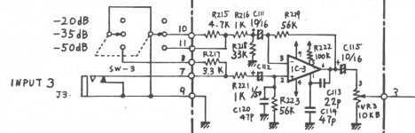
The circuit is not a pedal but the preamp for an old echo machine hence the oddball supply. Here's the preamp circuit. Elsewhere in the drawing you can see the power supply showing an upwards arrow for +14 and a -14V with a downwards arrow.
As for using dual supplies, if what constitutes the "virtual ground" for the circuit is actually not floating but tied to actual ground of all the stuff involved (guitar, amp, pedal power supply plugged into wall) won't that short something out? Or should a virtual ground be tied to a physical ground?
Thanks!
Attachments
I'm not sure I understand your question but the way it's normally done in guitar pedals is to create a virtual ground from the 9V battery / supply using a voltage divider, and no, that virtual ground isn't tied to actual ground, it's just used to bias the opamp at +4.5V so it can swing symmetrically up to 9V (or close) and down to 0V (or close), like this. And then of course you need to AC-couple the inputs and outputs, otherwise you would have a 4.5V DC offset there. Now, if you do use dual supplies, be it with two batteries or a proper symmetrical supply, then the middle point isn't virtual ground but actual ground (0V). Does that make sense?
I'm not sure I understand your question but the way it's normally done in guitar pedals is to create a virtual ground from the 9V battery / supply using a voltage divider, and no, that virtual ground isn't tied to actual ground, it's just used to bias the opamp at +4.5V so it can swing symmetrically up to 9V (or close) and down to 0V (or close), like this. And then of course you need to AC-couple the inputs and outputs, otherwise you would have a 4.5V DC offset there. Now, if you do use dual supplies, be it with two batteries or a proper symmetrical supply, then the middle point isn't virtual ground but actual ground (0V). Does that make sense?
Yes, I think I get it. Just seems weird to send a positive +9V to a physical ground. Does this make sense?

Ok, I see what you mean. Unless the two outputs of the supply are isolated, which they probably aren't, no, you can't do that, but it's very easy to stick with the single supply and do the virtual ground thing: voltage divider with two 100k resistors to get your virtual ground, cap from there to ground to make it low impedance at audio frequencies (100uF is typical), then connect R223 to virtual ground rather than ground, 7 to +9V, 4 to ground (actual) and you're done.
- Status
- Not open for further replies.
- Home
- Source & Line
- Analog Line Level
- Substituting Toshiba Op-Amp Into Circuit