Schematic
I lost the email with the connection to all concern schematics. Is it possible somebody can sent me the link?
Thanks
Albert
I lost the email with the connection to all concern schematics. Is it possible somebody can sent me the link?
Thanks
Albert
"dry joints" on the WM8804 ? Looks like that on the picture, at least the left pin connected to the crystal. Or a overheated WM8804 ?
Did you measure both 3.3 V regs ? BTW use either thinner wires for the connections or use Molex KK.
Mistery solved! The 50mhz oscillator was dead. Replaced with a 12 mhz that was on by drawer and it works.
Also discovered something interesting: when no clock input to ES9023 on pic 11 to GND measure 0.1V. Normally when ES9023 is connected to a working clock measure between pin 11 and GND 3.4V
atupi, good to hear that you worked it out 🙂
looking at your photos i was wondering about C17. Is thi a tantalum cap? Not sure about the BOM but i would think a mlcc (COG) might be a better choice here 😱
regards Daniel
looking at your photos i was wondering about C17. Is thi a tantalum cap? Not sure about the BOM but i would think a mlcc (COG) might be a better choice here 😱
regards Daniel
Boards received this afternoon. Thank you to JP and SB for taking their valuable time and effort to make this GB happen.
Sidney
Sidney
atupi, good to hear that you worked it out 🙂
looking at your photos i was wondering about C17. Is thi a tantalum cap? Not sure about the BOM but i would think a mlcc (COG) might be a better choice here 😱
regards Daniel
Yes it is a tantalum lityc 4,7uf. I've just followed the BOM recommended by the designers.
The choice for tantalum came as I used 1 µF ceramic for C17 and had the MIC oscillating. We would not like incidental cases of unsatisfied buyers so switched to higher ESR caps. The MICs are excellent but just never use ceramic caps at their outputs. You yourself even mailed me pictures of oscillating MICs in the same situation with your DAC so I wonder why you are asking that ?!.
You may try if you like and maybe it works OK. I had a few working OK too. You are right that the lower the ESR the better the XO is decoupled but the MIC does not join that conclusion.
Fellow builders, you can try to squeeze out max performance and we truly hope you can improve the design but don't expect us to react to every single change. We have to adhere to the "one size fits all" method so we play it safe to be able to cope with the GB while giving the builders a kind of guaranteed good result. In standard config (the alu pearl caps are not exactly standard but nevertheless...) you will build an excellent DAC for the price of a dinner for 2 in a restaurant. It will perform better than a lot of more expensive DACs. It is your challenge to improve the design if you like but we can't troubleshoot if things go wrong. For instance: I built several V2.6 DACs with different caps and they all sound different. Please take attention that I say " different" not " better". The only ones that really sounded better where the ones with Black Gate NX HiQ caps IMO.
The V3 final versions with the alu pearl caps have not yet been ABed with the older V2.6 with BG NX so who knows.....
Last edited:
Guys do you have any tips for my how to desolder/remove the oscilator ?
Hi,
the most elegant way to do ths is to use a so called "tweezer" iron (its basically two solder irons in one). Not too expensive on the bay.
I once did it succsessfully using a twisted wire as a solder-tip, bending one end to some kind of fork, so it would touch all four solder-points of the oscillator.
The removed part is probably gone then (due to overheating) but as you describe it, its dead anyway.
Regards,
Mickie
Last edited:
Put a very thin knife like a scalpel under the XO at one of the corners and then desolder the closest pin, then move knife to another corner and desolder next pin etc. Rude method but if you don't have SMD tools I guess there is no easy method.
Hi All
I'm waiting for delayed parts and Subbus parcel to be delivered (Parts/PCB/ES9023).
I've done my best to make it quick but sometimes it didn't go the way you've wished.
I'll give more informations soon, I hope.
Sorry for the delay.
Regards
Phil
I'm waiting for delayed parts and Subbus parcel to be delivered (Parts/PCB/ES9023).
I've done my best to make it quick but sometimes it didn't go the way you've wished.
I'll give more informations soon, I hope.
Sorry for the delay.
Regards
Phil
meeting with Subbu
Hi to everyone,
I met Subbu at a local coffee shop this morning and picked up my v3 boards. He let me know that the final shipments went out yesterday (Saturday) so everyone should be getting their boards soon. As a builder of a couple of the v2.6 dacs along with an earlier prototype of the v3 boards, I can reassure you that it's worth your wait. I've played around with parts quite a bit and have some suggestions to tweak things beyond the recommended parts in the BOM. But I think everyone should start with the BOM so that they have a baseline before substituting.
We all owe Subbu a debt of gratitude for the very large effort he put into this group buy. Unless you've managed a large group buy, you probably can't understand the magnitude of the task that Subbu took on. He sacrificed a lot of his spare time along with the time of his family, and all of this for no money - just out of a desire to contribute to the diy community.
Subbu - thank you very much!
---Gary
Last edited:
Hi Gary, Subbu indeed did a lot of work. I prototyped and drew the PCBs but I am really glad I did not have to run the GB 😉 Thanks Subbu !
I agree but ...considering the fact that many are not that experienced in removing the already soldered SMD parts maybe it is wiser to let us know your choices and results if they are significantly better than the results when using stock parts. If I would build only one DAC I'd better use the right stuff directly than ruining a PCB !
But I think everyone should start with the BOM so that they have a baseline before substituting.
I agree but ...considering the fact that many are not that experienced in removing the already soldered SMD parts maybe it is wiser to let us know your choices and results if they are significantly better than the results when using stock parts. If I would build only one DAC I'd better use the right stuff directly than ruining a PCB !
Last edited:
Hi Gary, Subbu indeed did a lot of work. I prototyped and drew the PCBs but I am really glad I did not have to run the GB 😉 Thanks Subbu !
I agree but ...considering the fact that many are not that experienced in removing the already soldered SMD parts maybe it is wiser to let us know your choices and results if they are significantly better than the results when using stock parts. If I would build only one DAC I'd better use the right stuff directly than ruining a PCB !
JP - sorry for not also acknowledging your contributions. You obviously were the creator of this entire project and deserve all of our thanks.
Regarding my tweaking of the V3 - mine was an early prototype of the V3 and I tried out a lot of things. I built this last May, so my description of the changes is about 6 months old but I think still pretty accurate. I was able to compare it to my V2.6 and also a V3 using the alternate SAL-RPM caps that you built. Having multiple versions to compare to made it possible to study the effect of different changes in a controlled manner, so I feel fairly confident in the results.
Tier 1 - most important change from the BOM
Upgrade C22 - the electrolytic cap for Avcc of the ES9023. I really like polymer caps and I find that the sound got better as I increased the size of this capacitor. I ended up using a 470uf 16v Nichicon capacitor. I think it was Nichicon part #493-3019-ND, Digikey 493-3019-ND. You can get away with lower voltage parts (6.3v or 10v). Panasonic and UCC also make good sounding polymer caps.
For best sound, I also recommend adding an output buffer such as the JG filter/buffer.
Tier 2 - next level of importance. C35 - the cap for the NEG terminal of the ES9023. I played around with different values of C35 and found that I got best sound with a value of 4.7uf. I like the Wima 4.7uf 50v polyester MKS2 caps. Mouser part # 505-MKS2-4.7/50/10.
I also found some benefit by increasing the size of C4 - the SPDIF input coupling cap. I used the BOM 0.1uf cap and put a 3.3uf 50uf Wima polyester in parallel. Mouser part # 505-MKS23.3/50/10. I mounted this from the bottom of the board since I was worried about fitting it on the top. In hindsight, it would have fit on the top of the board if I mounted the 0.1uf SMD cap first and then mounted the Wima on top of the 0.1uf cap.
Tier 3 - small benefit. Use better quality caps for the 10uf electrolytics for the WM8804 and ES9023 - C8, C13, and C21. Either use polymer electrolytics such as Nichicon PLF1E100MCL2 (Mouser # 647-PLF1E100MCL2) or Wima polyester. I used the Wima 10uf 50v caps (Mouser # 505-MKS210/50/20) but these take up more real estate and must be mounted from the bottom.
Tier 4 - changes I made that I don't think were worth the trouble. I tried a SAW oscillator for the 50Mhz clock and I liked the sound of it but I'm not sure it's really that much better. Since it's a different pad out than the current clock, it was very difficult to solder this one in. I used Kyocera KC5032A50.0000CM0E00 which is available from Digikey.
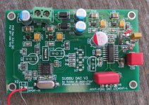
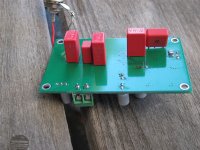
I've attached pictures of the top and bottom of my build so you can see how things went together. It's not that neat with parts on both sides but it's quite mechanically stable and sounds very good.
---Gary
Attachments
Last edited:
Wow ! I missed a lot. Thought everyone had moved over to the Build Thread. Are we going to continue to post in both threads?
Anyho, here's a link to a SMD removal technique that works quite well. I bought separate packages of flux and alloy as opposed to the kit. Will last for years at the pace I'm using it.
Anyho, here's a link to a SMD removal technique that works quite well. I bought separate packages of flux and alloy as opposed to the kit. Will last for years at the pace I'm using it.
I just saw the earlier photo of the PS where B1 is raised from the board. I mounted mine tight. Is that going to cause a problem?
Hi to everyone,
I met Subbu at a local coffee shop this morning and picked up my v3 boards. He let me know that the final shipments went out yesterday (Saturday) so everyone should be getting their boards soon. As a builder of a couple of the v2.6 dacs along with an earlier prototype of the v3 boards, I can reassure you that it's worth your wait. I've played around with parts quite a bit and have some suggestions to tweak things beyond the recommended parts in the BOM. But I think everyone should start with the BOM so that they have a baseline before substituting.
We all owe Subbu a debt of gratitude for the very large effort he put into this group buy. Unless you've managed a large group buy, you probably can't understand the magnitude of the task that Subbu took on. He sacrificed a lot of his spare time along with the time of his family, and all of this for no money - just out of a desire to contribute to the diy community.
Subbu - thank you very much!
---Gary
Thanks Gary. Like Gary mentioned, the last batch was dropped off at the post office today morning. Let the fun of building the DAC begin and hope everyone enjoys the "Subbu DAC".
Cheers!
Subbu
- Status
- Not open for further replies.
- Home
- Group Buys
- "Subbu DAC V3 - ES9023/WM8804 SPDIF & Power Supply PCB" Group Buy