I implemented the Scullcom design, wrote about it here. (main point was about identifing changes to a cheap voltmeter he used.
https://www.diyaudio.com/community/...ohm-meter-0-2v-voltmeter.379126/#post-6840566
https://www.diyaudio.com/community/...ohm-meter-0-2v-voltmeter.379126/#post-6840566
I could not find your reference but I did find this guide which is pretty comprehensive: https://www.seaward.com/gb/downloads/Guide to Low Resistance Booklet.pdf It shows pretty much all the alternatives and describes the limitations.
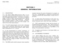
I'm also attaching the description of the 4328A from the manual that also describes the issues in measuring low value resistances.
I'm also attaching the description of the 4328A from the manual that also describes the issues in measuring low value resistances.
Attachments
It is a compromise between high current techniques that heat the DUT along with pulsed measurement complexity and possible damage to DUT, to measuring low signal levels along with noise suppression. Both ways have been used with high tech methods - the ESR method I use is based on a synchronous detection technique that has been around for decades with sub-milliohm accuracy and rejection of noise/frequencies other than the excitation frequency used, and work in very noisy energised environments where noise dominates the test signal. In contrast, some tests for continuity aim to validate the ability of the DUT to actually pass a suitably high current like 10A for electrical safety/earthing reasons. For some applications I'd frown even on pulsed currents where the test current level was quite large, as that is getting in to a whole new area of DUT safe operating area capability and repetitions.This is how it is done in industry, complying with agreed standards of measurement.
The res bridge I show, is accurate to uOhms, has a direct 200mV FSD (as JMFahey does also), making it fit standard metering.
Trust me, if you are measuring 10 mOhm, and then unless you wish to measure a resistor at 10mOhm and very very low wattage, it is rhe best solution.
Using a microOhmeter, with a tiny excitation current, is vulnerable to all sorts of 'other ' effects, interference, and inductive loads should be measured in both polarities.
The typical use for a microohmeter of this accuracy is for large conductors, where 10A won't have any significant effect (think 100A capable cabling, earth bonding etc)
The best part is, you don't seem to realise that this is what we are already doing: supplying controlled current to a resistance, to measure voltage drop.
But it works better if you think outside the lab, and lab grade equipment, where uOhms are in the noise at the bottom of their capability
Lastly, the difficulty of obtaining unsullied measurements in the uV or lower level is precisely the reason that in industry there are standard for the current sourced into various load resistances, such as 100mA for less than 2 Ohm, 1A for 20 to 200mOhm and 10A for loads less than 20mOhm.
In fact, we regularly test the armature reistance of megawatt scale DC machines, at circa 500A or more, in exactly the same way, dictated by BS EN standards 🤔
in that case, there is a real heating that can occur, so speed of measurement is key
Heat definitely has effect.
It is something that IF you can control, you control
And if you can't, then you measure temperature, before during and after a test.
Then compensate for resistance rise by temp rise.
All quite easy to do
It totally depends if resistance measurement has to be accurate to 0.1%
or
If you are trying to remove the influence of everything and if so, then LNO2.
But that's hardly necessary here is it?
mondo, the concern is that your post #18 only stated that high current measurement techniques were valid, and even referenced a standard to support that view. And post #20 went on to continue to push the view that high current measurements were the only valid test method to use.
No as I clarified in an earlier post,mondo, the concern is that your post #18 only stated that high current measurement techniques were valid, and even referenced a standard to support that view. And post #20 went on to continue to push the view that high current measurements were the only valid test method to use.
Appropriate current for the load.
When dealing with less than 20 mOhms, 10 Amps excitation is pretty appropriate, as best compromise between accuracy and minimising heating effects.
My point being that whatever load you wish to measure, exciting the load with a current, which in turn converts to a measurement voltage of between 0.1 and 0.2Volts, is the simplest and most reliable way to secure High accuracy resistance readings with the absolute minimum of self heating errors.
So with extraordinary resistances, say 1M, to be measured to the same degree of precision, if there is every a reason to need to know a 6 digit resistance to ten ohms accuracy, well then the excitation current become the issue.
In the real world.
The method is at least 100 years old and used for that reason.
- Home
- Design & Build
- Equipment & Tools
- Sub-ohm digital Ohmmeter