check out my post #23 under
https://www.diyaudio.com/community/threads/diodes-and-vbe-multipliers.385184/page-2
and the last URL there.
https://www.diyaudio.com/community/threads/diodes-and-vbe-multipliers.385184/page-2
and the last URL there.
Maavilloso estra aquí. El tema con el DIODO STABISTOR STV4H. Se puede reemplazar exitosamente. SMXSTB400. Es configuable a STV2H , STV3H STV4H. Comparto este video para todos aquellos que deseamos epara de manera optima, estos amplificadores que sus partes poseen especificaciones que ahoa es muy dificil encontar. Mil gracias. Espero no trasguedir las norrmas, compartiendoles este LINK. https://www.google.com/search?q=REE...#fpstate=ive&vld=cid:57128865,vid:GQe1ZqOmR3s
Maavosa Estra here. The theme with the Stabistor STV4H diode. It can be replaced successfully. SMXSTB400. It is reliable to STV2H, STV3H STV4H. I share this video for all those who want to optimally ePara, these amplifiers that their parts have specifications that Ahoa is very difficult to find. Thank you. I hope not transmit the norrms, sharing this link.
English please
dave

diyAudio moderation team
Wonderful to be here. The subject with the STABISTOR DIODE STV4H. It can be successfully replaced with the SMXSTB400. It is configurable to STV2H, STV3H, STV4H. I share this video for all those of us who want to repair in an optimal way, these amplifiers that their parts have specifications that are now very difficult to find. Thank you. I hope I do not transgress the rules, share this LINK.... https://www.google.com/search?q=REE...#fpstate=ive&vld=cid:57128865,vid:GQe1ZqOmR3s
Last edited by a moderator:
The description under
https://old-fidelity-forum.de/thread-35874.html
is good but it's way too complicated for me.
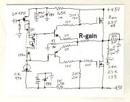
I prefer a Vbe multiplier with e. g. a BD135 (for heat sink mounting) and two resistors so as one pot resp. variable resistor for adjust idle current. Very important is the location of the pot - it must be connected (together with a serial resistor) between base and emitter of the BD135.
After an exact adjustment of the quiescent current, I check the resistance of the pot and replace it by a fixed resistor. Until this day I haven't observe a thermal runaway after doing this.
https://old-fidelity-forum.de/thread-35874.html
is good but it's way too complicated for me.
I prefer a Vbe multiplier with e. g. a BD135 (for heat sink mounting) and two resistors so as one pot resp. variable resistor for adjust idle current. Very important is the location of the pot - it must be connected (together with a serial resistor) between base and emitter of the BD135.
After an exact adjustment of the quiescent current, I check the resistance of the pot and replace it by a fixed resistor. Until this day I haven't observe a thermal runaway after doing this.
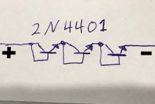
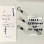
3x2N4401 - yes, it certainly is a interesting solution.
I hope this thread is helpful:
Audiokarma, EchoWars, Feb 4, 2010
It's a long thread, but I hope people get clarity from it.
I hope this thread is helpful:
Audiokarma, EchoWars, Feb 4, 2010
''Replacing The STV-3H and -4H Diodes''
https://audiokarma.org/forums/index.php?threads/replacing-the-stv-3h-and-4h-diodes.279530/It's a long thread, but I hope people get clarity from it.
I am not sure if i’d be using internal tooth lock washer type solder lug vs a regular flat tinned copper solder lug which has more contact area
But as long as the mmbt4401 Vbe is similar to a stv that’s all that really matter.
The bias generators using stv usually have a small adjustment range.
Many time folks change the silicon in the output stage which changes the required bias generators min,max, even using the original stv do not provide the proper adjustment range.
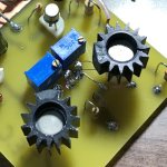
I already went to that thread and got bad response, basically run off, so thought I would try this. Yes, the flat lugs would be better. I didn't have any so just flatened the toothed ones and put some Silicon grease on the end. The thing is that the change in temperature is slow, so just about anything would work as long as connecting wires are quite small, and a good flat head screw. Here is photo of the latest amp part I used the idea, and they track perfectly, and it is a very common cheap transistor. I epoxied them to the heat sinks making sure insulated from them. one on each of them. Outputs are Lateral FETs which don't seem to need any compensation.
Attachments
- Home
- Amplifiers
- Solid State
- STV-4H AND STV-3H diodes array