Please forgive my ignorance, but I'm really wondering about this. I have been just starting to use Win ISD and I'm wondering if I'm missing some fundamental point. Here's an example:
Using a Tangband W8-740c (8" woofer), which has the following T/S parameters:
Fs28 Hz, Vas 23 Liters, Qts .30, Xmax 12mm
For a sealed enclosure, the program shows an optimum Vb of 0.178 cu. ft. with an F3 which is approximately 65 Hz.
For a vented enclosure, the program shows an optimum Vb of 0.306 cu. ft. which yields an F3 of approximately 38 Hz.
Here's the problem - Using the vented enclosure, it specifies a 4.02" diameter vent - with a length of 6.109 Ft. !!!!! Surely, this can't be for real. Are we supposed to adjust this for 1/4 wavelength or less?
Clearly, I'm doing something basically stupid, don't understand the program, or I'm missing the point altogether and should go buy some Bose speakers to use as firewood while I have a beer and think about it.
Can someone here point me in the right direction?
Thanks!!!
I'm simulating it and getting the same results. In fact thats why I haven't ordered that driver yet. I'm a little iffy about the Tang Band specifications. Most of their drivers graph really, really well for what they cost. So they either know what they're doing or they stretch it to make sales.
As for the 6 ft pipe, I'm getting that too. You could try using a smaller diameter port. Just remember to make sure the mach speed is less than whatever so it doesn't make noise. Also remember you can move the port to the outside and also put bends in it to fit it in. But with such a small volume you won't get very far. That's why I question these TB drivers. Says right in the data sheet that they're meant for ported enclosures though.
Pete
Some drivers just don't model well and lead to enclosures that are physically impossible to build (or work for that matter)
The specs could be incorrect but I've personally tested drivers that then model to impossible enclosures.
The specs could be incorrect but I've personally tested drivers that then model to impossible enclosures.
Netgeek:
A) You can use larger than optimum boxes. In this case I would suggest 0.5 Ft³.
B) Drone Cones, (Passive Radiators), were invented for cases where vents seem impossible.
C) I can't model one yet, but if you want to start a new thread, someone is likely to help you to see what a Transmission Line looks like with this woofer.
Stephen D
That's true but not the case here. This driver is actually modeling quite well & as would be expected of such a low Q driver of it's size tuned as low.
Here's the low down.
For sure physics are pushing against you when trying to achieve low tuning & small box symultaneous in a ported enclosure because as box volume goes down port length must go up for same tuning & port cross section. Also as for port alone, as port cross section goes up length goes up to maintain same tuning.
Usually things work out though for a given speaker diameter because smaller speakers can generally use smaller cross section port, & that is where the main error is in this case.
netgeek;
The 4" diameter port is way more than need be. Running a 100 watt input test sim in WinISD Pro & viewing the port air velosity graph shows that a 2.5" port will do. Modeling for QB3 alignment in WinISD Pro I get similar (insignificantly diferent) numbers than you with a 4" pipe but the 4" is just a default setting WinISD is throwing out at you. It's up to you to tailor the port cross section & length as small as you can get it keeping an eye on port air velocity.
keep in mind a QB3 is not the only alignment choice or even necessarily an optimum alignment (as often stated) for this or any other case. The range is infinite,.. but anyway for a QB3 alignment I come up with a 0.29 cubic ft box volume & tuning of 36.8 Hz. With that & a 2.5" diameter port I get a port length of 31.66". Yes, still quite long but manageable with some tricky design. There is also plenty leeway to raise the box volume some & still get a very good freq response curve & power output allowing port length to be shortened further. Experiment with little larger box & watch what it does to shrink port length & how well response graph looks. Do this until you reach a satisfactory compromise, though it will still be fairly long port length to box size ratio in this case. Remember port volume displacement is to be added to the alignment volume to equal total volume of box (also along with speaker displacement volume).
For this case I might use rectangular port, fashioned as integral part of cabinet walls. Front baffle 9"x9" then form a maze of 9" high walls to form cabinet exiting as port. Would all & all end up a very small woofer with good SQ. This speaker models well for ported but walks on the edge & challenges the designer.
Volenti said:Some drivers just don't model well and lead to enclosures that are physically impossible to build (or work for that matter)
The specs could be incorrect but I've personally tested drivers that then model to impossible enclosures.
That's true but not the case here. This driver is actually modeling quite well & as would be expected of such a low Q driver of it's size tuned as low.
Here's the low down.
For sure physics are pushing against you when trying to achieve low tuning & small box symultaneous in a ported enclosure because as box volume goes down port length must go up for same tuning & port cross section. Also as for port alone, as port cross section goes up length goes up to maintain same tuning.
Usually things work out though for a given speaker diameter because smaller speakers can generally use smaller cross section port, & that is where the main error is in this case.
netgeek;
The 4" diameter port is way more than need be. Running a 100 watt input test sim in WinISD Pro & viewing the port air velosity graph shows that a 2.5" port will do. Modeling for QB3 alignment in WinISD Pro I get similar (insignificantly diferent) numbers than you with a 4" pipe but the 4" is just a default setting WinISD is throwing out at you. It's up to you to tailor the port cross section & length as small as you can get it keeping an eye on port air velocity.
keep in mind a QB3 is not the only alignment choice or even necessarily an optimum alignment (as often stated) for this or any other case. The range is infinite,.. but anyway for a QB3 alignment I come up with a 0.29 cubic ft box volume & tuning of 36.8 Hz. With that & a 2.5" diameter port I get a port length of 31.66". Yes, still quite long but manageable with some tricky design. There is also plenty leeway to raise the box volume some & still get a very good freq response curve & power output allowing port length to be shortened further. Experiment with little larger box & watch what it does to shrink port length & how well response graph looks. Do this until you reach a satisfactory compromise, though it will still be fairly long port length to box size ratio in this case. Remember port volume displacement is to be added to the alignment volume to equal total volume of box (also along with speaker displacement volume).
For this case I might use rectangular port, fashioned as integral part of cabinet walls. Front baffle 9"x9" then form a maze of 9" high walls to form cabinet exiting as port. Would all & all end up a very small woofer with good SQ. This speaker models well for ported but walks on the edge & challenges the designer.
Stephen D
Also port can be totally external of woofer box, perhaps integrated as part of podium for MH speakers or something like that. 😉
Also port can be totally external of woofer box, perhaps integrated as part of podium for MH speakers or something like that. 😉
Try 20L box 8cm ID port Fb 31.72Hz (that results in approx 65cm port and the freq response when port resonance is taken into effect is much smoother! Sorry I'm a metric person, and didn't take the time to work out the box volume to be the same, just went with what unibox came up with (12.6L) and played a bit and came up with 20L.......
I modeled it with .5 ohm series resistance in Unibox.
Tony.
I modeled it with .5 ohm series resistance in Unibox.
Tony.
Attachments
Thanks for the responses - a relief to know that I'm not really losing my mind (well, at least not on this issue 🙂 )...
I'd be interested in any thoughts on using this same driver in a sealed enclosure with the goal of reproducing anything from about 100 Hz and below (to as low as possible).
The project is to take something like the Parts Express BR-1 configuration, roll it off at around 100 Hz, and then graft it on to a "subwoofer" that would give some additional punch to the lower frequencies. What started this was a friend's desire to put together some inexpensive speakers for an HT setup that would meet some pretty rigorous requirements in terms of space and "SAF" factor. In other words - relatively cheap, relatively small footprint, etc. Discrete subwoofers will not be allowed !! 🙂 So, the goal is to design some small "towers" (which tentatively would make the "SAF-approved" list) and which are sort of "full-range". SP levels are modest, particularly since there will be four of these things in a small room (with the option to expand to six later). My friend's interest is primarily in music content, while his wife is after the Home Theater stuff.
Originally, I wanted to build a quasi-dipole thingy, but cost and space won't allow it.
The current plan is for a 3-way config using active crossovers and EQ (if need be) - all of it powered by embedded "gainclone"-type amps. So, the subwoofer section can be "tweaked" (ala Elliot or Linkwitz) to extend the F3.
Any comments/suggestions are most welcome!
Thanks,
Bill
netgeek said:So, the subwoofer section can be "tweaked" (ala Elliot or Linkwitz) to extend the F3.
Any comments/suggestions are most welcome!
Thanks,
Bill
Since the sub is only 84 dB to begin with, I sure hope that none of your active tweaking involve lowering the output level to achieve a smooth frequency response. You have a low SPL per watt to start with.
If you want low bass I think you are going to need to go with vented with this driver. doesn't seem to model very well in a sealed enclosure. Although I admit that even a 65cm port in a 20L vented enclosure would be a challenge 🙂
Tony.
Tony.
Stephen D
Tony's suggested tuning above is a pretty good optimum compromise between max bass extension with minimum dip in the passband. It looks like about -1.5dB dip before the port tuning brings it back up nicely. With a port tuning of 31.72 Hz it wouldn't be the most ideal HT sub but would get by. After about a half octave below port tuning a ported speaker begins to move wildly because the port & speaker are out of phase at that point & unloading each other so it might could stand a infrasonic filter below 23-24 Hz if used for HT (Really not all that much down there anyway even for HT). You could also squeeze a little lower tuning out of it yet if you want at the expense of a little more dip in the upper passband. Would optimize better as a music woofer but could straddle the fence. Funny the woofer I use now for my living room HiFi + HT is an dual chamber (Augsburg style) ported with 8" and with the low port tuned at 31 Hz. I built it about 10 years ago & it's held up fine without an infrasonic filter & will literally shake my walls.
This Tangband does lack a little in the efficiency spec.
It is not a sub for sealed design if you want low bass. This is at home in a ported box.
Here is the Tangband in a 28 liter box with 31 Hz tuning. Power into 4 ohms is 100 watts.
The green line is the SPL
The purple line is the cone excursion.
The red line is the impedance.
As you can see, the dip is at the point where impedance is high, hence actual power is low. So if you want to add a little extra voltage to the gainclone, you can easily make an equalizer circuit that will not use up power. The dip is easily correctable.
This graph is made by Subwoofer Simulator, a fine freeware written by our own member, F4ier.
Attachments
More Volume = More Sensitivity
Increasing both volume and sensitivity is the 4th Order Bandpass.
Though it looks like it has a sharp peak, this should blend in with a midbass enclosure with an F6 of 55 Hz or so. Highly possible with a 5" vented mid.
Sensitivity is increased by 4 dB, from 84dB to 88 dB.
As before, this is the graph that assumes a drive wattage of 100 watts.
This time, I added room gain. The upper green line is the output with average room gain. The lower green line is the output without room gain.
The upper green line is the SPL with room gain.
The lower green line is the SPL withoutroom gain.
The purple line is the cone excursion.
The red line is the impedance.
The box measurements are:
Vented chamber: 20 liters
Sealed chamber: 30 liters
Tuning frequency: 40 Hz.
Notice the cone excursion only goes into nonlinear range beneath the passband, and can be controlled by a filter, possibly the one on the sub amp.
Attachments
Stephen D
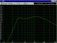
Just to illustrate there seems to be pretty much consensus between programs as regards calculation algorithm. Here's a vented SPL graph from WinISD Pro with identical box size, tuning & input wattage settings as done by kelticwizard in Subwoofer Simulator. For the record, when I input Tony's settings into WinISD Pro I get pretty close to the same response graph as he also. I must say I do like the way Subwoofer Simulator & Unibox can show the plots for different parameters such as SPL/cone excursion/impedance simultaneous in one graph. Makes convenient for posting results of all parameters. WinISD as yet can't do that. Must page through the different graphs, though it can show multiple alignments with different speakers & boxes simultaneous in one graph for easy comparison.
Just to illustrate there seems to be pretty much consensus between programs as regards calculation algorithm. Here's a vented SPL graph from WinISD Pro with identical box size, tuning & input wattage settings as done by kelticwizard in Subwoofer Simulator. For the record, when I input Tony's settings into WinISD Pro I get pretty close to the same response graph as he also. I must say I do like the way Subwoofer Simulator & Unibox can show the plots for different parameters such as SPL/cone excursion/impedance simultaneous in one graph. Makes convenient for posting results of all parameters. WinISD as yet can't do that. Must page through the different graphs, though it can show multiple alignments with different speakers & boxes simultaneous in one graph for easy comparison.
Attachments
I could get close but not quite the same with Unibox. Had to play with the fill and leaks, and take out the port resonance to get close.
I like the range of graphs available in Unibox, but it doesn't have a all in one graph like Stephen mentioned.
One thing I will say though, I was wondering why I had a bit of a dip at 500Hz when I measured (crudely) my existing speakers (originally modeled in SW, or boxplot can't remember which). When I modeled in Unibox, there was a response dip which was almost identical to the one I was getting in real life. The other modeling programs I had used showed it being flat.
Tony.
Attachments
Stephen D
Interesting.
I was noticing in those 1st graphs you put up, the 2 sharp
narrow band high Q notchess in the upper pass band (just above the hump, in the range where the VC inductance shows up as the typical sloping roll off above mid bass).
What parameter is it that Unibox is deriving that from? Port resonance/Q...? I've never seen anything like that in WinISD & I don't see it in your last graph so I assume it's a legitimate function of some parameter that Unibox is picking up on & making a prediction on. Has to be one of the user definable parameters you tweaked out on the last graph. Port resonance would be my guess since the second dip appears to be a harmonic of the 1st. I may just have to try that program out, but I hate having to load Excel back on my puter. Downloaded Subwoofer Simulator today but haven't given it a whirl yet. I wish one of these freeware would add simulation for dual chambered reflex. LSPcad does but it cost $, though not outrageously much. I really admire & appreciate those that can develop programs like these.... & to offer it up free... makes me feel like a kid turned loose in a toy store!
😀
wintermute said:When I modeled in Unibox, there was a response dip which was almost identical to the one I was getting in real life. The other modeling programs I had used showed it being flat.
Tony.
Interesting.
I was noticing in those 1st graphs you put up, the 2 sharp
narrow band high Q notchess in the upper pass band (just above the hump, in the range where the VC inductance shows up as the typical sloping roll off above mid bass).
What parameter is it that Unibox is deriving that from? Port resonance/Q...? I've never seen anything like that in WinISD & I don't see it in your last graph so I assume it's a legitimate function of some parameter that Unibox is picking up on & making a prediction on. Has to be one of the user definable parameters you tweaked out on the last graph. Port resonance would be my guess since the second dip appears to be a harmonic of the 1st. I may just have to try that program out, but I hate having to load Excel back on my puter. Downloaded Subwoofer Simulator today but haven't given it a whirl yet. I wish one of these freeware would add simulation for dual chambered reflex. LSPcad does but it cost $, though not outrageously much. I really admire & appreciate those that can develop programs like these.... & to offer it up free... makes me feel like a kid turned loose in a toy store!
😀
Yep it is port resonance, there is a tick box so you can add it in or leave it out. The last graph I took it out so that it matched closer to the winisd and subwoofer simulator.
It's interesting to note the effect that port diameter has on it too! The peak (due to port resonance) when I modeled the 6' port was something to behold 🙂. Gives you something else (for better or worse) to worry about when modelling 🙂, but I guess its good to find out about it before you have started, rather than after you have finished!
I haven't gone to the trouble of working out how unibox works (I suspect its all macros done in VB)
As well as the graphs I have shown it has impeadence, step response, peak cone excursion and port air speed (although as far as I am aware it's not possible to get all of them on one graph).
Also on the main design tab it tells you straight away if your port diameter is too small, you don't have to look at any graphs.
It doesn't do everything (No XO design, cabinet dimentions or the like), and yeah its a bit of a pain that it uses excell (not a prob for me I bought a copy while I was studying at the student price), But I reckon its worth a look.
I'm also going to have a look at the subwoofer simulator!
edit: BTW the dip I was seeing in the speaker I tested recently wasn't from the port resonance, I'm suspicious about the size of the dip that unibox shows, peak I can understand, but a trough that deep seems a little unlikely. The dip I had was driver related, which SW and boxplot didn't show in their simulations. The effect of port resonance with my vifa 10" drivers hardly even shows up on the graph, so I guess it depends a lot on the area of the port and the tuning of the box.
Tony.
- Status
- Not open for further replies.
- Home
- Loudspeakers
- Multi-Way
- Stupid WinISD question