Hello all!
I have previously built a Simple SE, and a TSE-II. Have had the parts to build a Simple P-P for years and finally got around to building it.
After firing it up for the first time and checking the voltages, I ran into a bit of a strange problem:
I'm sure that I did something stupid, but just can't seem to figure out what. Any help would be much appreciated!
-- Pete
I have previously built a Simple SE, and a TSE-II. Have had the parts to build a Simple P-P for years and finally got around to building it.
After firing it up for the first time and checking the voltages, I ran into a bit of a strange problem:
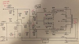
- The issue happens on both channels equally (so whatever I did wrong, I did it consistently wrong at least!)
- Music going in at roughly .75 Vrms
- Music coming out the 8 ohm tap at 10mV (perfectly clear, sounds good, just super super quiet!)
- Checked all of the components with a meter to the parts list / schematic.
- Power supply portion seems good: B+ 330v, 5v = 5v, Heaters = 6.9v.
- Thinking it may be in the first stage of amplification = g1 of the EL84 is only getting .25v to ground. After coupling caps, almost no voltage differential between R111 & R115
- Tried it with and without feedback. In both UL and Pentode wiring.
- Running JJ ECC81 and EL84 tubes.
I'm sure that I did something stupid, but just can't seem to figure out what. Any help would be much appreciated!
-- Pete
Attachments
I think I figured out the issue, but don't have time to update the board tonight. Put in a 75 ohm resistor in the input plate load instead of a 75k. Oops. Was doing a bit of research and Rknize said that he had better luck with a 150k in this position. What is the general consensus on this since I'll be switching the part out anyway? Thanks!
sgtnoah,
Glad to hear you figured it out - well done.
Regarding the 75k vs. 150k load resistor, I think George‘s 75k is closer to the ideal operating point for a 12AT7 than what 150k would give you. Eli Duttman of “El Cheapo” fame believes ‘The 12AT7 sounds GOOD with 200 to 220 V. on the plate and IB = 3 mA. 3 mA. thru 50 KOhms drops 150 V. So, 355 to 360 V. of B+ is "perfect". ‘ With a B2 supply on the SPP of around 320Vdc and 3 ma flowing through 75k you will have ~95v on the plates. I have not checked the loadlines for the SPP, but I assume it is biased for less than 3ma. Perhaps you could measure and tell us.
I expect that a 150k load resistor for the VA will not be optimal and 75k will be better, especially since the phase inverter is dependent on the directly coupled voltage it gets on it’s grid for biasing. That said, one can’t argue with what someone else thinks he hears.
The real issue is that there are lots of "things" being sold as 12AT7's these days, and some bear little resemblance to the original tube. The resistor values in the original SPP board were chosen the old fashioned way. I took a large box full of 12AT7's and similar tubes like the 6201 and a pile of resistors and picked the combo that worked the best with a wide variety of tubes. Almost all of the tubes were old stock 12AT7's from several US manufacturers or old stock military "12AT7 equivalents." The JJ 12AT7 was not available in the US at the time, and JJ's 12A_7 tubes are "different." Most look more like a 6922/6DJ8 than a US made 12AT7.
A pair of 150 K's will put the phase inverter current in the less than 1 mA range which can sound a bit anemic with a Sylvania 12AT7.
A pair of 150 K's will put the phase inverter current in the less than 1 mA range which can sound a bit anemic with a Sylvania 12AT7.
Thank you both for the input! I put a 75k in each position and it sounds good. I'll measure the bias and adjust as needed, now that I'm in the ballpark.
Still need to hook it up to the scope and figure out the best amount of feedback and associated bypass cap and do some other final tweaking.
Thank you George for such fine designs - I've thoroughly enjoyed building (and listening to) all three of the amps that you offer.
-- Pete
Still need to hook it up to the scope and figure out the best amount of feedback and associated bypass cap and do some other final tweaking.
Thank you George for such fine designs - I've thoroughly enjoyed building (and listening to) all three of the amps that you offer.
-- Pete
