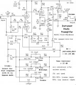
Built this Instrument Preamp from plans by Fred Nachbaur. Amp works except I can not get the tone controls to work. Being a newbie ( other than a simple repair) I'm not sure where to start. I've checked and rechecked my wiring and I really can't find anything that looks out of place. One mod was I eliminated the bypass and ran directly to the tone controls. Any suggestions?
Freds Web Link http://www.dogstar.dantimax.dk/tubestuf/instpre.htm
MoreBass
Freds Web Link http://www.dogstar.dantimax.dk/tubestuf/instpre.htm
MoreBass
Attachments

Ensure that the phasing of Sw1 sections is correct.
Did you fit a component in the position of Ctwk? If so, remove it for now.
Did you fit a component in the position of Ctwk? If so, remove it for now.
Tube preamp
Pinouts of my pots look OK and I eliminated SW1ab completely (bypassing the flat response switch. Just ran signal directly to the tone stack). No cap in the tweek before C3 either. Being my first post and new to this I appreciate your responses.
Perhaps a better question about my nonfuntioning tone controls is should this schematic work as designed? From Freds web site on this project he said he did not construct this project but felt it is correct in design. I haven't found anyone else who may have built this preamp to compare notes, and I know there are a lot of knowedgeable people on this forum, so if others can say this design is solid, I'll assume the problem is on my end and troubleshoot my construction.
Thanks,
MoreBass
Freds Web Link http://www.dogstar.dantimax.dk/tubestuf/instpre.htm
Attachments
I was a personal friend of Fred (RIP) and can indeed attest to it's working good. Even got PCB's here for it 🙂
Tube Preamp
Geek, I appreciate your response and from what I've read, Fred was a wealth of knowledge and most willing to share it, that's what prompted me to build his design. By eliminating the possibility of a flaw in the schematic, I know the problem is on my end. Was not aware boards were available but building it point to point and constructing an enclosure was part of the fun and education to understand tube design.
When time permits, I'll go over my build and post any progress.
MoreBass
No problem! Good luck 🙂
IIRC, DigitalJunkie has the majority of those PCB's now. Maybe he'll shoot you a couple for a buck or two.
IIRC, DigitalJunkie has the majority of those PCB's now. Maybe he'll shoot you a couple for a buck or two.
I too think it should work, and have confidence in Fred's work.
For the tone controls to work, there must be gain - lots of it as they are in the feedback path.
Try removing the feedback take out C15, and see if the gain jumps right up (it may go unstable)..
Also, are the regulator tubes glowing? If not, measure some voltages and report.
For the tone controls to work, there must be gain - lots of it as they are in the feedback path.
Try removing the feedback take out C15, and see if the gain jumps right up (it may go unstable)..
Also, are the regulator tubes glowing? If not, measure some voltages and report.
Studio Preamp
Busy Holidays, but found time to trouble shoot.
In my first post I mentioned I deviated from the orig. design by eliminating the bypass switch, so thinking that may be the problem, I installed the switch for tone/bypass with no better results. Switching to tone gives me good sound but no control of tone; bypass produces more noise and ocsillation.
Bypassed C15 resulting in distorted low volume(neon bulbs did not light), so I probed some voltages which are represented on the left. On the right are recommended voltages from Freds Phono Preamp(similar design, not sure if applicable).
B+ 366V 360-390V
Plate V1A( bottom of R6) 204V 190-210V
Cathodes V1(pin 3&8) 31.5V 26-32V
Grid Supply V1A(+ side C2) 29.5V 1.5V less than Cathodes
Grid Supply V1B(+ side C4) 29.9V 2V less than Cathodes
Grid V2(pin 2) 207V Same as V1A(190-210V)
Grid V2(pin 7) 288V N/A
Cathode V2(pin 3) 202V 1.5V higher than Grid V2
Plate V2 (pin 1) 288V 290-310V
Filaments +- 6.5V +- 6.3V
R9 and L1 191V N/A
C15 (- side) about 30V N/A
Thanks Again for the Suggestions
MoreBass
Leaky caps? I saw the RA-100 this was designed for and Fred used low-leakage sweep/SMPS caps.
Also, 12AT7's are kinda finicky unless you're used to them.
Also, 12AT7's are kinda finicky unless you're used to them.
my "fred's studio pre"pcb layout-no tone control
this is my creation on fred's studiopre design:http://www.geocities.com/fidelityfx/download/Preamp_Fred_Nachbaur.pdf
I'm still new with tubes, any suggestion I would be happy to hear
Regards,
Opik
this is my creation on fred's studiopre design:http://www.geocities.com/fidelityfx/download/Preamp_Fred_Nachbaur.pdf
I'm still new with tubes, any suggestion I would be happy to hear
Regards,
Opik
Geek said:I was a personal friend of Fred (RIP) and can indeed attest to it's working good. Even got PCB's here for it 🙂
I miss Fred. i didn't know him personally, but i miss his online presence and antics.
i miss him too
I've learn a LOT from fred's design & publication, I wish someone could improving his web without changing the original content, I tought that the Godzilla projects and the rest of his projects will be more easier to understand.
I've learn a LOT from fred's design & publication, I wish someone could improving his web without changing the original content, I tought that the Godzilla projects and the rest of his projects will be more easier to understand.
Hello, I built the Nachbaur's Studio Preamplifier preamp and it works but I am concerned about the heater to cathode voltage. I run heaters on AC and elevated them to about 75Vdc. I get a heater to cathode voltage (measure with DMM on 12at7 pins) up to -235V. I believe it's not good though Fred's design doesn't elevate heaters at all.
I am confused. Is there a problem or is it ok?
Should I elevate heaters' to 250V or so?
Please help!
Thanks in advance.
I am confused. Is there a problem or is it ok?
Should I elevate heaters' to 250V or so?
Please help!
Thanks in advance.
Attachments
That design appears to seriously violate the heater-cathode voltage spec for the 12AT7. I note that in the write-up he says that he hasn't actually built it himself.
Yes, the spec says 90V.
Increasing the heaters' DC reference to 250V or so should fix the problem? Should it be safe or is it too much?
Thanks in advance.
Increasing the heaters' DC reference to 250V or so should fix the problem? Should it be safe or is it too much?
Thanks in advance.
The heater is not interested in its voltage from ground, just the voltage from the cathode. You need to think about what happens during warm-up. You may need two heater circuits, one (grounded) for 12AX7 and the other for 12AT7 - attach the latter to V2A cathode?
At moment I have 6v AC supply referenced to 90vdc by two 100 ohm resistors.
Regarding the two supplies:
I have a 0-6-12v winding but I doubt I could wire two separate AC heaters' supplies because the 0-leg should be common to both. Correct?
Perhaps running one of them on DC should do the trick?
If affirmative, please help me to understand how to do:
1) Wire 6v DC to V1
2) Wire 0-12v AC to V2 and tie one leg to V2A cathode.
Correct?
Many thanks for your attention.
You can't connect one secondary winding to two different DC bias values. If you have two separate secondaries then there is no problem.
- Status
- Not open for further replies.
- Home
- Live Sound
- Instruments and Amps
- Studio Tube Preamp