Hi guys,
I have an "entry level studio" condenser microphone SP-C1.
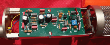
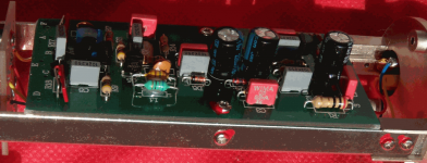
I want to mod or replace the preamp inside the capsule with the goal to have a lower noise floor. The preamp is made of 1 FET tranzistor and another 4 BJT.
All film caps are Polyester from WIMA or unbranded 10nF.
Soon i will post the schematic(i will try to copy it form the PCB traces) and some pics of the board and component values.
It looks well build but i want to make a better one.
current specs:
Noise: Line): 27dB (A weighted)---17dB
S/N: 77 dB
Does anyone have a diagram for a discrete or opamp hi-fi - premium condenser preamp/buffer?
It would use phantom power, i am also building a small mixer and i can implement custom "phantom power" special for this modded microphone.
I think i should have posted this topic the Analogue Source section.....
I have an "entry level studio" condenser microphone SP-C1.
I want to mod or replace the preamp inside the capsule with the goal to have a lower noise floor. The preamp is made of 1 FET tranzistor and another 4 BJT.
All film caps are Polyester from WIMA or unbranded 10nF.
Soon i will post the schematic(i will try to copy it form the PCB traces) and some pics of the board and component values.
It looks well build but i want to make a better one.
current specs:
Noise: Line): 27dB (A weighted)---17dB
S/N: 77 dB
Does anyone have a diagram for a discrete or opamp hi-fi - premium condenser preamp/buffer?
It would use phantom power, i am also building a small mixer and i can implement custom "phantom power" special for this modded microphone.
I think i should have posted this topic the Analogue Source section.....
Last edited:
Now it uses +48 Vdc, but if needed i could make it a split power supply of +15Vdc -15Vdc.
Also, from what i have learned is that the condenser capsule must be polarized with approximately 35V, usually this is done through a big resistor >1 G ohm.
Also, from what i have learned is that the condenser capsule must be polarized with approximately 35V, usually this is done through a big resistor >1 G ohm.
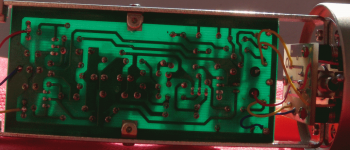
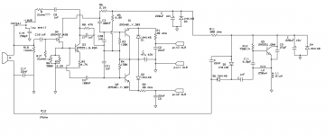
I managed to draw the diagram studying the PCB trace.
All resistors except R12 are 5%. Caps look real cheap. I would change them (except the resistors around the Q4 FET) I want a lower noise floor.
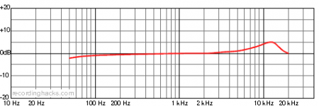
Wouldn't mined to also change the sound a little, a little to bright stock - look at the freq resp graph.
Any ideas?
All resistors except R12 are 5%. Caps look real cheap. I would change them (except the resistors around the Q4 FET) I want a lower noise floor.
Wouldn't mined to also change the sound a little, a little to bright stock - look at the freq resp graph.
Any ideas?
Attachments
Hi,
First, the circuit is mostly straight out of Neumann Mike, not a bad place to start I would add.
The noisefloor in Condensor Mikes is pretty much determined by the impedance (capacitance) of the Capsule, this is sufficiently large to cause significant noise. There are not many options to deal with that in circuit.
You could try different Fets, but I suspect the 2N5457 will already be within a few dB of the theoretical limit.
So one of the two optiosn is to get the mike closer so you get more SPL, the other would be to change the capsule for one with more level AND more capacitance (in both cases at least 3dB/1.414 times more).
You could try adding some EQ to create some HF rolloff in the Microphone, however I somehow doubt that this is really the problem, if a bit of EQ does it, you can always add this in post production.
It may be worthwhile poking a 'scope probe around the circuit to see if you get any breakthrough from the small chopper that creates the polarisation voltage for the Capsule, if so shielding/better filtering may be needed.
But it may be very well a limitation of the microphone capsule, so again, the only way to fix this may be to replace the capsule.
Ciao T
First, the circuit is mostly straight out of Neumann Mike, not a bad place to start I would add.
I managed to draw the diagram studying the PCB trace. All resistors except R12 are 5%. Caps look real cheap. I would change them (except the resistors around the Q4 FET) I want a lower noise floor.
The noisefloor in Condensor Mikes is pretty much determined by the impedance (capacitance) of the Capsule, this is sufficiently large to cause significant noise. There are not many options to deal with that in circuit.
You could try different Fets, but I suspect the 2N5457 will already be within a few dB of the theoretical limit.
So one of the two optiosn is to get the mike closer so you get more SPL, the other would be to change the capsule for one with more level AND more capacitance (in both cases at least 3dB/1.414 times more).
Wouldn't mined to also change the sound a little, a little to bright stock - look at the freq resp graph.
You could try adding some EQ to create some HF rolloff in the Microphone, however I somehow doubt that this is really the problem, if a bit of EQ does it, you can always add this in post production.
It may be worthwhile poking a 'scope probe around the circuit to see if you get any breakthrough from the small chopper that creates the polarisation voltage for the Capsule, if so shielding/better filtering may be needed.
But it may be very well a limitation of the microphone capsule, so again, the only way to fix this may be to replace the capsule.
Ciao T
- Status
- Not open for further replies.