350 Studio layout is some interested I will share
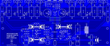
Here is a layout of this famous Studio 350 from Silicon Chip and I basically copy from a bmp image into my Sprint Layout 5 and I think is completed if some one see any mistake please let me know so I can fix it right away, I'm planning to order 2 boards later, 😀 good day guys!
Regards
vargasmongo3435
Attachments
Last edited:
For what it's worth I've built a pair of '350s (using boards from RCS) and I think the (objective and subjective) performance is excellent for such a simple and venerable topology. The PCB layout is very nice and probably accounts for much of this - the designer Peter Smith seems to be one of the few they've had working there that produced good PCBs and he presumably came up with the clever EMF/distortion cancelling layout of the power and output tracks. You do need to be careful with the grounding of the heatsinks though - I noticed some instability that disappeared when I attended to this.
The sound through my B&W801s is very civilised, no harshness, with an excellent and wide soundstage. To my ears it's much better than any of the Lin topology designs that they have produced over the years. The only amp I like better from my collection is the Leach, however I have to say the Studio 350 is a little "cleaner" if not quite as natural.
The sound through my B&W801s is very civilised, no harshness, with an excellent and wide soundstage. To my ears it's much better than any of the Lin topology designs that they have produced over the years. The only amp I like better from my collection is the Leach, however I have to say the Studio 350 is a little "cleaner" if not quite as natural.
Here is a layout of this famous Studio 350 from Silicon Chip and I basically copy from a bmp image into my Sprint Layout 5 and I think is completed if some one see any mistake please let me know so I can fix it right away, I'm planning to order 2 boards later, 😀 good day guys!
Regards
vargasmongo3435
Looks ok from a quick glance, however I would remove the dead copper fill areas and keep it as close to the original as possible. Also make sure you've left room for holes to cable tie the power wires under the board. Good luck with it!
BTW I used 2SA1016 instead of 2SA1084 for the input pair.
Thanks owdeo for the tip
That is a nice tip well yeah you right I then take away the dead copper to keep it as original *** possible, don't mind about those drawings and letters it will be change by the original ones is just art, thank you kind of you of give a wisdom opinion I appreciate that owdeo 😛
That is a nice tip well yeah you right I then take away the dead copper to keep it as original *** possible, don't mind about those drawings and letters it will be change by the original ones is just art, thank you kind of you of give a wisdom opinion I appreciate that owdeo 😛
You're welcome. Actually even though I still think you should remove the copper fills it might be good to keep an electrical connection to the small flag heatsinks with some removable links allowing each to be connected to gnd. In my experience having these heatsinks grounded can improve stability (I suppose by having a defined capacitance between the transistor tab and ground). Stops them potentially acting as antennas too. At least something to try if you have problems anyway.
Also I'm not sure about having the extra "chassis gnd" connection on the PCB. The star earth point is on the board so be careful about internal earth loops if you build them as a stereo amp in one chassis. I would suggest following the power wiring detail exactly as in the article as this has been tested by SC.
Also I'm not sure about having the extra "chassis gnd" connection on the PCB. The star earth point is on the board so be careful about internal earth loops if you build them as a stereo amp in one chassis. I would suggest following the power wiring detail exactly as in the article as this has been tested by SC.
One more thing: the 68pF miller capacitor needs to be close to the transistor, however in the original it's so close to the transistor's heatsink that the capacitor is heated by it (they run quite warm) which not a good thing. If you can I'd try to space it out by a couple more mm or maybe swap the positions with the 4k7 resistor next to it.
Ok, I will keep that in mind my friend, the chassis GND to be honest I don't know why I came out with that idea maybe I still have the Army military idea that all have to be grounded into chassis you know in any electronic device, I'm going to change the layout and keep as original as possible , and you give me nice idea of having the heat sink grounded that is good thanks again owdeo is a pleasure to interchange ideas.
Regards
vargasmongo3435
Regards
vargasmongo3435
Welcome 🙂 I just checked the article and their power supply wiring scheme earths the amplifier via the "0V" connection to the power supply reservoir caps - this point is then connected to mains earth. So no need for the extra connector.
The article shows the connection between the reservior caps as the "0V" point, but it would be better to take a "T" off from this point to the chassis nearby and connect both the mains earth and the amplifier 0V line to this instead, as there are large currents flowing in the wire joining the caps and you don't want these causing ripple on the actual 0V reference.
The article shows the connection between the reservior caps as the "0V" point, but it would be better to take a "T" off from this point to the chassis nearby and connect both the mains earth and the amplifier 0V line to this instead, as there are large currents flowing in the wire joining the caps and you don't want these causing ripple on the actual 0V reference.
- Status
- Not open for further replies.
- Home
- Amplifiers
- Solid State
- Studio 350