Ranks may differ up to one rank, so during normal operation differences between Vpo are not important.
The unequal heating up is due to this fault condition. Swap the two and see if the heat spot swaps too.
In the ServMan page 4 points g and h: the solder connection to enable service mode and the drive boards and v-fets removed.
The power supply should operate as expected.
Proceed with points i to n. Point L: the drains are not connected yet!
The drive boards should operate as expected.
Proceed with point o to q. If the fault condition happens, a fet is not well.
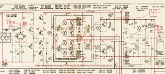
Notice there's a small difference on the pcb to straighten the operation of the p- and n-channel fets: R140 (47k).
The unequal heating up is due to this fault condition. Swap the two and see if the heat spot swaps too.
In the ServMan page 4 points g and h: the solder connection to enable service mode and the drive boards and v-fets removed.
The power supply should operate as expected.
Proceed with points i to n. Point L: the drains are not connected yet!
The drive boards should operate as expected.
Proceed with point o to q. If the fault condition happens, a fet is not well.
Notice there's a small difference on the pcb to straighten the operation of the p- and n-channel fets: R140 (47k).
Attachments

I already did that very early in the repair process. It does as expected.Swap the two and see if the heat spot swaps too.
Proceed with point o to q. If the fault condition happens, a fet is not well.
All SITs are OK. I now think the issue lies with a driver board as the recapper complained that replacing one channel proved problematic. As I did not observe the exact voltages of the pluthora of supply rails there could be an issue with the +/-77 V rails. I have yet to investigate.
Did notice that resistor but dismissed it as unimportant. It may not be.Notice there's a small difference on the pcb to straighten the operation of the p- and n-channel fets: R140 (47k).
ok / ok / ok, all agreed.
I'm curious what the results are, step by step, when following that sequence in the ServMan.
It should give a clue about the chicken-egg dispute.
I'm curious what the results are, step by step, when following that sequence in the ServMan.
It should give a clue about the chicken-egg dispute.
That's another clue. These driver board are mounted upon the main board. Is that with connectors, solderings? Maybe small damages or failing connections. Tracks all continious, solderings ok... numerous causes. An electron microscope could help.that replacing one channel proved problematic
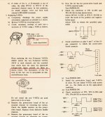
I got to step k. The waveforms in service mode for both channels are smack on as per manual:


However, when switching on the PWM takes its sweet little time to start to oscillate:

This could be due to the DBT. I will redo this test without it.
I also found the six power rails are somewhat off. This is prolly due to the service mode. The values are: 118.2, 79.3, 76.5, -76.0, -79.1, -118.3. The two +/-77 V rails are way too high but this is prolly because they're not loaded.
However, when switching on the PWM takes its sweet little time to start to oscillate:
This could be due to the DBT. I will redo this test without it.
I also found the six power rails are somewhat off. This is prolly due to the service mode. The values are: 118.2, 79.3, 76.5, -76.0, -79.1, -118.3. The two +/-77 V rails are way too high but this is prolly because they're not loaded.
Most probably.due to the DBT
1% to 3% off spec, nothing to worry about. In the ServMan, the +/-77 rails are also mentioned as +/-80, so that was the designed value.the six power rails are somewhat off
Huh. Even without DBT it takes 3 s for the PWM to spring to life in service mode:Most probably.

I can hardly see this as an issue as while the amp output is at +rail the speaker relay will keep it from doing any damage. But I still haven't gotten anywhere near the fault causing the issue of it not starting properly on DBT...
This is getting nowhere. I will try something else. I will install current limiting resistors in series with the +/-80 V rail, install a single pair of SITs and power up without DBT. See what happens.
Last edited:
A seriuous issue indeed... hmm...without DBT it takes 3 s for the PWM to spring to life in service mode:
A challange, I'm along this puzzle - 2bcontSee what happens.
I have a result. With two fat 68R resistors in both 80 V rails it started up!

I don't understand the significance of the bump in the drive voltage after 3 s. It coincides with the delay in service mode. Weird.
Edit: not weird, it is just the speaker relay engaging. Also, the voltage drop across the two resistors is 5 V.

The left channel has no transistors or driver board. If this kludge is working I will move the resistor in place of TH402. When I'm satisfied it works correctly.
I don't understand the significance of the bump in the drive voltage after 3 s. It coincides with the delay in service mode. Weird.
Edit: not weird, it is just the speaker relay engaging. Also, the voltage drop across the two resistors is 5 V.
The left channel has no transistors or driver board. If this kludge is working I will move the resistor in place of TH402. When I'm satisfied it works correctly.
Last edited:
Full disclosure: there was no fault. What must have happened is that when I fixed the PSU I tested it on dummyload with DBT. Once the PSU was OK I connected the amp itselt. When the recapper did his work he tested with DBT. So we learned that this is one of those amps that will not work on DBT. I put everything in and all is OK. I get a healthy 242 W into 8R albeit on one channel.
Maybe we should start a DBT refuseniks database.
Maybe we should start a DBT refuseniks database.
- Home
- Amplifiers
- Solid State
- Stuck with Sony TA-N88B