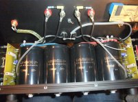
Unknown reason of constant blown fuses at model 3.0s located in the 230VAC line to transformer's primary input forced me to find out the differences to the reliably operating model 3.0. The following was observed in detail:
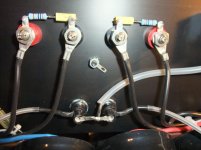
With this power amplifier (independent mains transformers for each channel), the fuses between the mains connection and each mains transformer, located at the back plate, often blown away - sometimes only those from the right channel or only from the left channel, sometimes also those from both channels.
As a first step, I switch-on the power amplifier at another place with good daylight conditions near the window without connected loudspeakers and pre-amplifier.
The fuses do not blown here and the DC voltage values as well as the quiescent current match with the 3.0 model on both channels (offset between +/- 2,5mV and 5mV.
The next step was to set up the power amplifier at its usual location near the other audio components, but now also without connected speakers and pre-amplifiers.
One of the fuses blown again immediately.
Faulty wall socket for mains?
No, because now connected to the same wall socket as near the window, the fuses of both channels blown away again.
What's going on here ?
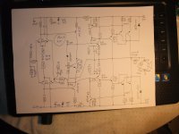
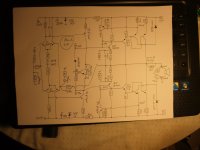
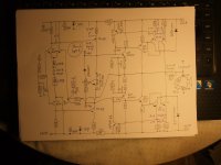
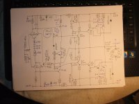
Next I examined the differences in detail between the models "3.0s" and "3.0" (of model 3.0 I create a circuit diagram with the DC measured values a long time ago).
The following differences to the model 3.0 I note (check out also the schematics of the images No 1-4):
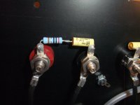
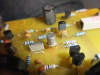
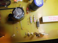
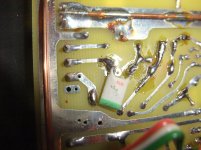
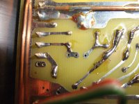
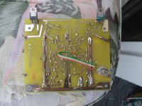
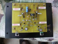
1) a. Low-pass filter capacitor is missing in the input (not used on PCB - go to image No 2 and 4 in post #2 - the one from last image and image No 3 in post #2 I have added, the value in the 3.0 is 220pF)
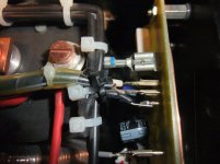
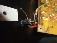
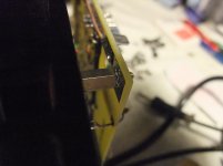
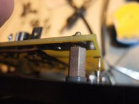
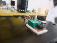
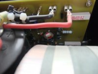
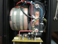
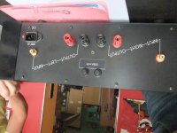
1) b. Enclosure (chassis) not electrically connected to circuit ground (no grounding cable soldered to the present soldering lug in the middle between the cinch input sockets and cinch input sockets of both channels insulated installed - go to image No 5) - therefore the chassis acts as an "antenna" for electrical interference fields of all kinds.
2) Input resistance reduce to 22K (47K for the 3.0)
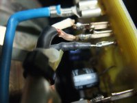
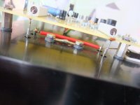
3) NFB resistance reduced from 1K to 820 Ohm and not on the circuit board but externally in the shrink tube in series to the separate cable to the GND star point on the main capacitors (2x33mF/80V) PCB-holes therefore not used. Go to image No 8+9.
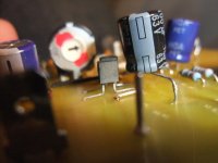
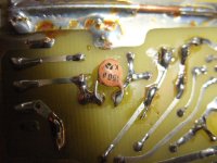
4) LTP resistor (15K) on the complementary input differential amplifier replaced by a constant current diode (possibly J508) in a TO92 outline - go to image No 7
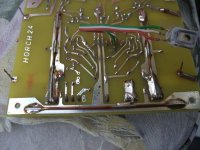
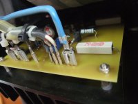
5) MPS-A42/MPS-A92 (for VAS stage, TO-92 outline in the 3.0) replaced by metal versions in the TO18 outline without printed type No - go to image No 1 in post #2
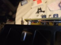
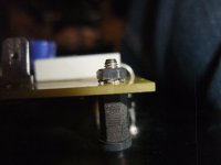
6) Series air coil with parallel resistor 4R7 at the output is missing (but Boucherot network on the speaker terminals at the back plate is present - go to images No 5+6)
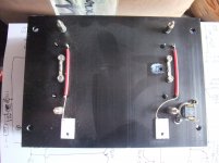
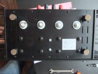
7) Bridge rectifier with single diodes in the TO-220 outline - presumably "fast-switching" or "fast recovery time" versions (printed type naming sanded off unfortunately) - see images under
Unknown TO220 Diodes (discrete Bridge Rectifier) for Horch 3.0S and Threshold 4000 (in model 3.0 two normal 35A bridge rectifier are in use on the bottom of the case).
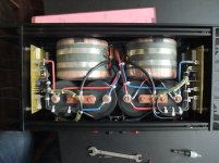
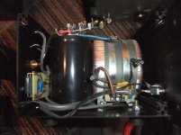
8) Another transformer with the same voltage and the same dimensions, but higher current delivery capability and thus higher value for VA (in both models class II versions with angle brackets are in use - probably made by German's transformer manufacturer "FG-Elektronik" - meanwhile taken over by Uber Uns – Sasse Elektronik)
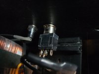
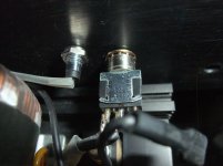
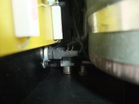
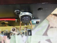
9) Inrush current limiter on the back of the mains connection plug (IEC inlet C14); missing on model 3.0 - see images in post # 41 under
The ultimate Inrush Current Limiter Solution for large Toroidal Transformers
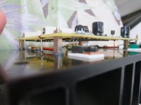
10) Toothed lock washer (to ensure a perfect electrical connection between the output transistors connected in parallel) on the top of the board (go to image No 9 in post #2) instead of on the conductor track side - go to image No 5-8 in post #2.
Here rises up the question of which differences were wanted and which differences were unwanted - in particular the differences under 1) are unwanted in my opinion and could be responsible for the blown away fuses, because this could be the reason for unwanted high-frequency oscillations which forces the highest possible current flow like with an interrupted VBE pot for adjusting the right value for quiescent resp. idle current.
Perhaps someone also has the model 3.0s in use and could see whether a cable leads away from the soldering lug by removing the dust cover.
And maybe someone already has repair and modification experience with it.
Thank you very much for any advice.
P.S.: for the used power devices in the TO-3 outline there exist only a small range - go to the TO-3 versions in post #1, under number 1) and 4) under
bipolar (bjt) transistor families for audio power output stages
Unfortunately all out of production (obsolete):
1) 2ST5949/2ST2121 250V 17A 250W
https://www.st.com/resource/en/datasheet/cd00178796.pdf
https://www.st.com/resource/en/datasheet/cd00171926.pdf
2) MJ21195/21196 and MJ21193/21194 250V 16A 250W
https://www.onsemi.com/pdf/datasheet/mj21195-d.pdf
https://www.onsemi.com/pdf/datasheet/mj21193-d.pdf
3) additional this older types: MJ15022/15023 200V 16A 250W
https://www.onsemi.com/pdf/datasheet/mj15023-d.pdf
https://www.onsemi.com/pdf/datasheet/mj15022-d.pdf
Are TO-3 versions still available resp.in ongoing production ?
With this power amplifier (independent mains transformers for each channel), the fuses between the mains connection and each mains transformer, located at the back plate, often blown away - sometimes only those from the right channel or only from the left channel, sometimes also those from both channels.
As a first step, I switch-on the power amplifier at another place with good daylight conditions near the window without connected loudspeakers and pre-amplifier.
The fuses do not blown here and the DC voltage values as well as the quiescent current match with the 3.0 model on both channels (offset between +/- 2,5mV and 5mV.
The next step was to set up the power amplifier at its usual location near the other audio components, but now also without connected speakers and pre-amplifiers.
One of the fuses blown again immediately.
Faulty wall socket for mains?
No, because now connected to the same wall socket as near the window, the fuses of both channels blown away again.
What's going on here ?
Next I examined the differences in detail between the models "3.0s" and "3.0" (of model 3.0 I create a circuit diagram with the DC measured values a long time ago).
The following differences to the model 3.0 I note (check out also the schematics of the images No 1-4):
1) a. Low-pass filter capacitor is missing in the input (not used on PCB - go to image No 2 and 4 in post #2 - the one from last image and image No 3 in post #2 I have added, the value in the 3.0 is 220pF)
1) b. Enclosure (chassis) not electrically connected to circuit ground (no grounding cable soldered to the present soldering lug in the middle between the cinch input sockets and cinch input sockets of both channels insulated installed - go to image No 5) - therefore the chassis acts as an "antenna" for electrical interference fields of all kinds.
2) Input resistance reduce to 22K (47K for the 3.0)
3) NFB resistance reduced from 1K to 820 Ohm and not on the circuit board but externally in the shrink tube in series to the separate cable to the GND star point on the main capacitors (2x33mF/80V) PCB-holes therefore not used. Go to image No 8+9.
4) LTP resistor (15K) on the complementary input differential amplifier replaced by a constant current diode (possibly J508) in a TO92 outline - go to image No 7
5) MPS-A42/MPS-A92 (for VAS stage, TO-92 outline in the 3.0) replaced by metal versions in the TO18 outline without printed type No - go to image No 1 in post #2
6) Series air coil with parallel resistor 4R7 at the output is missing (but Boucherot network on the speaker terminals at the back plate is present - go to images No 5+6)
7) Bridge rectifier with single diodes in the TO-220 outline - presumably "fast-switching" or "fast recovery time" versions (printed type naming sanded off unfortunately) - see images under
Unknown TO220 Diodes (discrete Bridge Rectifier) for Horch 3.0S and Threshold 4000 (in model 3.0 two normal 35A bridge rectifier are in use on the bottom of the case).
8) Another transformer with the same voltage and the same dimensions, but higher current delivery capability and thus higher value for VA (in both models class II versions with angle brackets are in use - probably made by German's transformer manufacturer "FG-Elektronik" - meanwhile taken over by Uber Uns – Sasse Elektronik)
9) Inrush current limiter on the back of the mains connection plug (IEC inlet C14); missing on model 3.0 - see images in post # 41 under
The ultimate Inrush Current Limiter Solution for large Toroidal Transformers
10) Toothed lock washer (to ensure a perfect electrical connection between the output transistors connected in parallel) on the top of the board (go to image No 9 in post #2) instead of on the conductor track side - go to image No 5-8 in post #2.
Here rises up the question of which differences were wanted and which differences were unwanted - in particular the differences under 1) are unwanted in my opinion and could be responsible for the blown away fuses, because this could be the reason for unwanted high-frequency oscillations which forces the highest possible current flow like with an interrupted VBE pot for adjusting the right value for quiescent resp. idle current.
Perhaps someone also has the model 3.0s in use and could see whether a cable leads away from the soldering lug by removing the dust cover.
And maybe someone already has repair and modification experience with it.
Thank you very much for any advice.
P.S.: for the used power devices in the TO-3 outline there exist only a small range - go to the TO-3 versions in post #1, under number 1) and 4) under
bipolar (bjt) transistor families for audio power output stages
Unfortunately all out of production (obsolete):
1) 2ST5949/2ST2121 250V 17A 250W
https://www.st.com/resource/en/datasheet/cd00178796.pdf
https://www.st.com/resource/en/datasheet/cd00171926.pdf
2) MJ21195/21196 and MJ21193/21194 250V 16A 250W
https://www.onsemi.com/pdf/datasheet/mj21195-d.pdf
https://www.onsemi.com/pdf/datasheet/mj21193-d.pdf
3) additional this older types: MJ15022/15023 200V 16A 250W
https://www.onsemi.com/pdf/datasheet/mj15023-d.pdf
https://www.onsemi.com/pdf/datasheet/mj15022-d.pdf
Are TO-3 versions still available resp.in ongoing production ?
Attachments
-
 DSCF8108.jpg801.8 KB · Views: 234
 -
 DSCF8107.jpg635.9 KB · Views: 258
 -
 DSCF8105.jpg600.3 KB · Views: 203
 -
 DSCF8106.jpg789.3 KB · Views: 221
 -
 Horch 3.0S Zobel-I.jpg986.8 KB · Views: 202
 -
 Horch 3.0S Zobel-II.jpg980.7 KB · Views: 134
 -
 DSCF8062.jpg978.7 KB · Views: 118
 -
 Horch 3.0S ext. NFB Resistor-II.jpg983.2 KB · Views: 110
 -
 Horch 3.0S ext. NFB Resistor.jpg987.6 KB · Views: 105
 -
 DSCF8052.jpg984.5 KB · Views: 161
Last edited:
more images
Attachments
-
 Horch 3.0S VAS TO-18.jpg977.6 KB · Views: 81
 -
 DSCF8070.jpg977.3 KB · Views: 73
 -
 DSCF8074.jpg990.8 KB · Views: 54
 -
 DSCF8072.jpg992.1 KB · Views: 66
 -
 Horch 3.0S External Toothed Lock Washers-IV.jpg977.1 KB · Views: 56
 -
 Horch 3.0S External Toothed Lock Washers-II.jpg857.3 KB · Views: 54
 -
 Horch 3.0S External Toothed Lock Washers-III.jpg983.1 KB · Views: 52
 -
 Horch 3.0S External Toothed Lock Washers.jpg869.3 KB · Views: 52
 -
 Horch 3.0S External Toothed Lock Washers-wrong.jpg978 KB · Views: 50
 -
 Horch 3.0S without PCB.jpg997.5 KB · Views: 57
continue
Attachments
-
 Horch 3.0S Capacitors.jpg1 MB · Views: 68
 -
 Horch 3.0S Main Switch.jpg979.8 KB · Views: 61
 -
 Horch 3.0S Main Switch-II.jpg985.8 KB · Views: 51
 -
 DSCF8022.jpg886.7 KB · Views: 58
 -
 Horch 3.0S PCB-II.jpg808.5 KB · Views: 91
 -
 Horch 3.0S PCB-III.jpg949.5 KB · Views: 64
 -
 DSCF8014.jpg684.6 KB · Views: 72
 -
 Horch 3.0S connection PCB-Heatsink-I.jpg904.9 KB · Views: 78
 -
 Horch 3.0S connection PCB-Heatsink-II.jpg685.7 KB · Views: 63
 -
 Horch 3.0S connection PCB-Heatsink-III.jpg734.5 KB · Views: 61
more images
Attachments
-
 Horch 3.0S PCB-I.jpg846.4 KB · Views: 89
 -
 Horch 3.0S bottom.jpg999.9 KB · Views: 89
 -
 Horch 3.0S con-.jpg980.3 KB · Views: 84
 -
 Horch 3.0S Con+.jpg862 KB · Views: 65
 -
 Horch 3.0S Front.jpg977.3 KB · Views: 76
 -
 Horch 3.0S open top.jpg989.8 KB · Views: 94
 -
 Horch 3.0S open top-II.jpg972.7 KB · Views: 149
 -
 Horch 3.0S rear.jpg997.2 KB · Views: 74
 -
 Horch 3.0S sticker.jpg983.5 KB · Views: 86
 -
 Horch 3.0S inrush current lim-VII.jpg1,013.4 KB · Views: 100
I bought MJ21193 & MJ21194 2 weeks ago from newark.com the US version of farnell.com . Date codes in '21 . $10.32 ea. All are painted MEX but the newark label says the 93 are COO MY instead of MX .Are TO-3 versions still available resp.in ongoing production ?
2) MJ21195/21196 and MJ21193/21194 250V 16A 250W
Newark also stocked MJ21195/96 . Wg-ski tells me one series is a select version of the other, but I can't tell which is the inferior part. There are slight difference in the typical gain curves; nothing in the guaranteed parameters.
Great analysis of possible deficiencies of the modifications.
Last edited:
I even have amps that have MJ15022 and 024 in the same parallel bank, that came from the factory that way. Only allowing 250 volt capable parts to be sold would have been a significant yield hit, judging by the fact that the 022 hasn’t gotten phased out yet. Differences between 21193 and 5 are even smaller - I don’t know why they even bothered unless it was Marketing’s decision. There is a bump in the SOA at 80 volts, but it’s only a BUMP, and not something that would compel me to use one over the other.
That particular amp topology likes to OSCILLATE. It doesn’t surprise me that there were changes over time as problems that weren’t there before crop up and they needed to “fix” them.
That particular amp topology likes to OSCILLATE. It doesn’t surprise me that there were changes over time as problems that weren’t there before crop up and they needed to “fix” them.
under
http://saba-forum.dl2jas.com/index....=1&s=ce864ac1000d85110bbc741e6a84c3444e3d26a4
are mentioned some hints
http://saba-forum.dl2jas.com/index....=1&s=ce864ac1000d85110bbc741e6a84c3444e3d26a4
are mentioned some hints
- Home
- Amplifiers
- Solid State
- Strip Down Power Amplifier Horch Model 3.0 and 3.0s; what TO-3 Power Output Devices?