I am currently using one half of a 12ax7 to swing about 50v peak-to-peak into a relatively high-impedance load. Bypassing the cathode resistor with a large value capacitor provides ALMOST enough gain to be driven by a smartphone line-out. As such, I need to add another stage — but I would like to take the opportunity to implement a negative feedback scheme to reduce the overall distortion.
Sidebar: While I'm certain that better performance could be achieved by adding additional tubes, I'd simply like to wring the most out of the two triodes available in the single 12ax7.
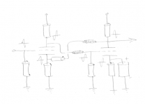
I have attached a sketch that is similar to some other circuit fragments I've found online. The feedback scheme was initially counter-intuitive since the signal on the plate of triode #2 is in phase with the cathode of triode #1 — but I suppose this has the effect of increasing the degeneration of the first stage. If this feedback was taken to the grid of triode #1, I presume it would oscillate. With this implementation, I'm not sure if it makes sense to keep the cathode bypass capacitor on triode #2 in place for higher gain — or whether it should be removed to let the degenerative feedback lower the distortion.
This is my starting point, but I'd love to hear any criticism of this scheme or suggestions for different implementations. It's also possible that I am completely wrong on all counts.
-Nick
Sidebar: While I'm certain that better performance could be achieved by adding additional tubes, I'd simply like to wring the most out of the two triodes available in the single 12ax7.
I have attached a sketch that is similar to some other circuit fragments I've found online. The feedback scheme was initially counter-intuitive since the signal on the plate of triode #2 is in phase with the cathode of triode #1 — but I suppose this has the effect of increasing the degeneration of the first stage. If this feedback was taken to the grid of triode #1, I presume it would oscillate. With this implementation, I'm not sure if it makes sense to keep the cathode bypass capacitor on triode #2 in place for higher gain — or whether it should be removed to let the degenerative feedback lower the distortion.
This is my starting point, but I'd love to hear any criticism of this scheme or suggestions for different implementations. It's also possible that I am completely wrong on all counts.
-Nick
Attachments
I am currently using one half of a 12ax7 to swing about 50v peak-to-peak into a relatively high-impedance load. Bypassing the cathode resistor
with a large value capacitor provides ALMOST enough gain to be driven by a smartphone line-out.
That's a pretty standard circuit, what gain and bandwidth are needed? It may be best to use the second cathode without the capacitor.
That's pretty standard, and implemented in both solid state and hollow state forms. The one improvement I'd suggest is an active plate load for the second half of the 12AX7. This type has a lot of gain (at least for a triode) but is hampered by a gigundous plate resistance (90K, nominal).
Active plate loading would improve output swing, increase voltage gain, and reduce the plate loading. That way, you could get the gain and avoid a cathode bypass capacitor, since there is no AC across the cathode resistor if the plate current is constant.
After that, it's a question of how much closed loop gain you need, the BW requirements, and Zload. Despite the reputation, the 12AX7A can perform with sonic excellence. Reports of disappointing sonic performance almost always go back to inadequate VPP and passive plate loads that are too small WRT the rp.
The feedback scheme was initially counter-intuitive since the signal on the plate of triode #2 is in phase with the cathode of triode #1 — but I suppose this has the effect of increasing the degeneration of the first stage.
-Nick
It is very easy to understand why the feedback negative, if you realise that V1 besides being a common cathode stage (input=grid, output = anode) also acts as a grounded grid amplifier (input = cathode, output=anode).
I am currently using one half of a 12ax7 to swing about 50v peak-to-peak into a relatively high-impedance load. I need to add another stage
but I would like to take the opportunity to implement a negative feedback scheme to reduce the overall distortion.
One problem of this circuit is with the feedback resistor loading down the output stage. You can also get excessive subsonic LF peaking
from the feedback resistor and its associated coupling capacitor because of this loading. What exactly is your load amplifier?
Last edited:
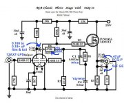
"Steal" the ZVN0545A source follower from the uploaded phono preamp schematic. Take the NFB from the "hot" connection to the O/P jack. Doing so deals with the stability issue "rayma" mentioned in his last post. Also, no cap. is needed in the NFB line.
Attachments
Thank you all for the prompt replies!
rayma — I need enough gain to swing about 50v peak-to-peak from a 1v RMS source. Bandwidth is about 300Hz to 20kHz.
Miles — I like the idea of using an active load (I've built solid state amplifiers with CCSs before, so I know this can work well), but I'm not sure it's worth stealing the triode from the input gain stage (assume there's just the one 12ax7 on the island).
costis_n — Looking at things from that perspective is illustrative.
rayma — I need to roll off the bass, anyway — I suppose I can compensate for the low frequency peaking by playing with the coupling capacitor between stages or the cathode bypass capacitor. I don't think the feedback resistor will cause excessive loading — it should be able to swing enough current in addition to the load.
Eli — I thought we were in the tube forum? 😀 I'm not sure if you are referring to the cap in my sketch or the cap in the phono circuit, but I think it could only be removed in my circuit if the other resistor values were sized exactly right so as to not upset the bias points.
"Steal" the ZVN0545A source follower from the uploaded phono preamp schematic. Take the NFB from the "hot" connection to the O/P jack. Doing so deals with the stability issue "rayma" mentioned in his last post. Also, no cap. is needed in the NFB line.
The follower solves that problem. Dyna's similar line stage (in their PAS preamp) used the "brute force" approach, heavily loading
the main output with a 62k resistor. About all you could say for that, is that it was cheaper than a follower stage and tube socket.
Yes, you can decrease the coupling capacitor after the first stage and largely eliminate the LF peaking (due to the feedback resistor
not being much larger than the second stage plate resistor). That capacitor will need to be at least an order of magnitude smaller than usual to do this.
What are you going to drive with this circuit?
Last edited:
Eli — I thought we were in the tube forum?
A FET is darned close to being a heaterless pentode. Electrically, FETs behave like tubes, not BJTs. Setting up a DC coupled enhancement mode MOSFET source follower is a "no brainer". 😀 It sounds damned good too. The ZVN0545A is perfect for use with wimpy tubes, like the 12AX7 and EF86. Note the tiny capacitances. I'm a pragmatist. I use tubes because they do many jobs, especially voltage amplification, far better than SS does.
I'm not sure if you are referring to the cap in my sketch or the cap in the phono circuit, but I think it could only be removed in my circuit if the other resistor values were sized exactly right so as to not upset the bias points.
Note the source follower's O/P coupling capacitor. That part isolates the jack from all the DC potentials. That's why another cap. in the NFB line is unnecessary. The follower's O/P coupling cap. is sized according to the I/P impedance of the following circuitry. The value shown in the schematic I uploaded works well into the IHF 10 Kohm "standard". The corner frequency of the high pass filter formed by the coupling cap. and the following circuitry's I/P impedance should be <= 5 Hz.
Here's another great sounding FET with exceedingly low Crss = 1.8pF typical.
http://aosmd.com/pdfs/datasheet/AOT1N60.pdf
I use it's bigger brother, the AOT2N60 to drive an 833C transmitter tube and it sounds fantastic. The 2N60 still only has 2.8pF Crss.
http://aosmd.com/pdfs/datasheet/AOT1N60.pdf
I use it's bigger brother, the AOT2N60 to drive an 833C transmitter tube and it sounds fantastic. The 2N60 still only has 2.8pF Crss.
A question to all of the source follower proponents:
What if the output triode's bias point had to be 5/6 of the B+ voltage (instead of the usual halfway point)?
Alternately, could I safely double the B+ to 600v if it is being dropped evenly across two triodes in an active load situation (I think the heaters might need to be floated)?
What if the output triode's bias point had to be 5/6 of the B+ voltage (instead of the usual halfway point)?
Alternately, could I safely double the B+ to 600v if it is being dropped evenly across two triodes in an active load situation (I think the heaters might need to be floated)?
Last edited:
It wouldn't matter to the MOSFET since it can swing almost rail to rail, unlike the triode.What if the output triode's bias point had to be 5/6 of the B+ voltage (instead of the usual halfway point)?
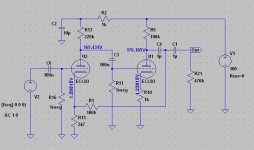
There's no need to use a capacitor in the NFB loop. It is not too hard to re-jig the dc conditions of the first stage so a straight pot divider from the second anode the the first cathode is the NFB network. Gets rid of LF instability and makes the circuit unconditionally stable at LF.
Cheers
Ian
Cheers
Ian
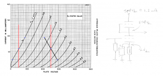
In the name of simplicity, would the following circuit be tenable? I realize the heaters would need to be floated. Assuming there was no load and the input signal was sufficient, would it at least work as drawn — swinging roughly +/-40v around the 250v bias point in a fairly linear manner?
Attachments
Question for Eli,
How would a LND150 (depletion) work as a substitute for the ZVN0545A? It also seems to have very low capacitances.
many thanks,
tim
How would a LND150 (depletion) work as a substitute for the ZVN0545A? It also seems to have very low capacitances.
many thanks,
tim
I realize the heaters would need to be floated.
It would be best have two different heater supplies with such a high B+, since the upper heater will have to be elevated by over 150V otherwise, too much for the lower triode.
It would be best have two different heater supplies with such a high B+, since the upper heater will have to be elevated by over 150V otherwise, too much for the lower triode.
This is not a problem. Assuming the heaters were fed and cared for properly, would the rest of the circuit operate as drawn? Would it offer any advantages over the original circuit with two gain stages and negative feedback?
In the name of simplicity, would the following circuit be tenable? I realize the heaters would need to be floated. Assuming there was no load and the input signal was sufficient, would it at least work as drawn — swinging roughly +/-40v around the 250v bias point in a fairly linear manner?
Looks like an SRPP with some bits missing. The top triode is still a heavy load for the bottom one so it will not be very linear.
Cheers
Ian
- Status
- Not open for further replies.
- Home
- Amplifiers
- Tubes / Valves
- Strategies for Implementing Negative Feedback in a 12ax7 Line Amplifier