1. Signal wire go to not no.5 but to no. 6.
Then, it goes thru a resistor to no.5.
Why?
(green one is coupling cap.)
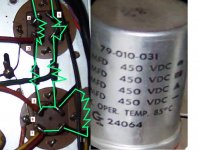
2. I am going to change two big aluminum
capacitors in PSU. However, I cannot understand
their wiring. What kind of capacitors is this?
how can I replace it?
Then, it goes thru a resistor to no.5.
Why?
(green one is coupling cap.)
2. I am going to change two big aluminum
capacitors in PSU. However, I cannot understand
their wiring. What kind of capacitors is this?
how can I replace it?
Attachments
1) I assume that it is the same amp in the post that was on the U/L question. Can you post a full schematic. My guess is that it is a grid bias R, in some fashion.
2) These are multi-section caps. One pin is for ground. and then the others are the + side of the cap. Usually there is a marking on the side of the cap that will indicate a color or symbol code to what terminal is to what section.
Does anyone know if there is a standard system to identify these guys, if that is not present?
Hope it helps
Matt
nop
thanks...
But it is different project.
This 6v6pp was made by Bogen, however, the 6v6SE
mentioned yesterday was made by myself.
I cannot find Bogen's original file schematic
in internet. I think it is almost the same as that
time's receiver such as H&K, Dynaco, etc.
Bass,Treble, Balance, Stereo-Mono, & Speaker-Headphone
switches are found. It uses P-K PI circuit. I am going to make
the circuit simple and replace rugged parts.
Anyway, i will upload some pictures of this Bogen
here and full schematic of 6v6SE in the 6V6SE
post.
Attachments
I see the 6v6'pp' now.
I can read. Really 🙂
🙂
I will see if I can dig up a schematic then for the Bogen. Then we can tell if that wiring in the socket is true or a mod.
Matt
I can read. Really
🙂 I will see if I can dig up a schematic then for the Bogen. Then we can tell if that wiring in the socket is true or a mod.
Matt
The resistor from pin 5 to 6 is probably a grid stopper. Usually if it were say, a grid leak, it would go from pin 5 to chassis (a tab off the socket's mounting saddle).
The capacitors are usually stamped on the outside as to the ratings. A geometric symbol accompanies the ratings, and these are stamped on the bottom of the can. The case is common and grounded by the chassis; I've never seen a twist-lock that has a seperate ground pin.
Tim
The capacitors are usually stamped on the outside as to the ratings. A geometric symbol accompanies the ratings, and these are stamped on the bottom of the can. The case is common and grounded by the chassis; I've never seen a twist-lock that has a seperate ground pin.
Tim
Tim,
that is good info on the caps. I havn't used the twist locks much. So that is good to know.
as to the grid resistor, I guess I am not getting why it would be across the cathode to the grid, with the full signal coming into the cathode. The stoppers that I have seen, have just been in series with the signal, attached directly to the grid pin on the socket.
I am sure that I am not getting something, please explain 😕
TIA
Matt
Thanks..
Thank you for infos......really thanks..
1.
how many capacitors are needed if i replace them of new ones?
1. from rectifier / to opt
2. to screen grid of 6v6
3/4/5. to 12ax7/6eu7
6. ground
(green line in picture means connection. coil shape means resistor. )
2. Tim! why no.6 is used? I hear that it is critical in making noise even if it is it is blocked inside tube.
Attachments
Tried to look up a schematic. no luck.
For the caps, the easiest way is to just get some new twist lock cans. There are some decent ones out there. I would start at antique electronics supply. http://www.tubesandmore.com
You could replace them with discrete caps if that is what you want. Although I can't be certain, it looks as if the cap on the bottom of the picture has each of two sections paralled. if that is the case, you could replace them with one cap of their combined value. This was a common practice when using multi-caps to get the values needed.
Matt
thanks
for your effort.
good luck.
newkirklabs said:Tried to look up a schematic. no luck.
For the caps, the easiest way is to just get some new twist lock cans. There are some decent ones out there. I would start at antique electronics supply. http://www.tubesandmore.com
You could replace them with discrete caps if that is what you want. Although I can't be certain, it looks as if the cap on the bottom of the picture has each of two sections paralled. if that is the case, you could replace them with one cap of their combined value. This was a common practice when using multi-caps to get the values needed.
Matt
for your effort.
good luck.
I did find a schematic for a dynaco amp with pp6v6's in the output. You had indicated that your amp might be similar. It had a 1k r tying the signal to the grid. They were not connected in anyway to the cathode
Hope this can help a little
http://www.triodeel.com/dyna6bq5.gif
Matt
Hope this can help a little
http://www.triodeel.com/dyna6bq5.gif
Matt
newkirklabs said:....as to the grid resistor, I guess I am not getting why it would be across the cathode to the grid, with the full signal coming into the cathode. The stoppers that I have seen, have just been in series with the signal, attached directly to the grid pin on the socket.
Hi,
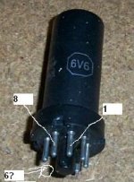
pin 5 is a grid
pin 6 on 6v6 isn't connected, doesn't exist (picture) IMO
pin 8 IS cathode pin.
This resistor is a grid-stopper. Pin 6 on socket is obviously used just like mechanical-soldering support-point.
Regards,
Milan
Attachments
More stuff to dig
Thanks moams...
Anyway, Wow....I cannot understand this circuit.
I am totally overwhelmed.
http://user.chol.com/~ecwcpt/mule/1.jpg
http://user.chol.com/~ecwcpt/mule/2.jpg
http://user.chol.com/~ecwcpt/mule/3.jpg
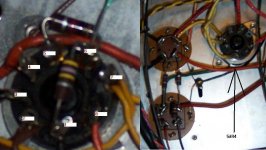
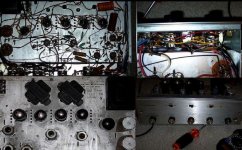
1.
Click the following URLs. (It is more than 100k.)
The picture will show you power output stage of
Bogen (6v6 pp).
You can see numbers marked. Follow it from 1 to 8.
Seem to be normal. See the 8. Big orange
capacitor (250mf/50V) is shared by cathodes
of all other three 6v6s. Ok, I heard about
cathode sharing....You can see an orange wire
relays it.
2.
But!!!!! No resistor for bias. You may say it is not self
but fixed bias. However, I cannot find any circuit for
fixed bias. The orange wire is just connected to the other
cathodes. It measures 17V in cathode of 6V6.
3.
And can see [?] marked in 1. jpg?
Yes, it goes to no.4 of
12AX7 for phono preamp. (Line/Phono are separated
in this Bogen. two 12AX7 are used.) No other connection to
No. 4. A wire is connected in No.5. However, I don't know
where it goes. In No. 9, there is nothing soldered.
4. 3.jpg is full picture of phone pre-amp part (very big file).
See no3. of the upper 12AX7. It is connected with no.4 and
no.6. What's going on here?
____________________________________________
I have never heard about this odd wiring.
Thanks moams...
Anyway, Wow....I cannot understand this circuit.
I am totally overwhelmed.
http://user.chol.com/~ecwcpt/mule/1.jpg
http://user.chol.com/~ecwcpt/mule/2.jpg
http://user.chol.com/~ecwcpt/mule/3.jpg
1.
Click the following URLs. (It is more than 100k.)
The picture will show you power output stage of
Bogen (6v6 pp).
You can see numbers marked. Follow it from 1 to 8.
Seem to be normal. See the 8. Big orange
capacitor (250mf/50V) is shared by cathodes
of all other three 6v6s. Ok, I heard about
cathode sharing....You can see an orange wire
relays it.
2.
But!!!!! No resistor for bias. You may say it is not self
but fixed bias. However, I cannot find any circuit for
fixed bias. The orange wire is just connected to the other
cathodes. It measures 17V in cathode of 6V6.
3.
And can see [?] marked in 1. jpg?
Yes, it goes to no.4 of
12AX7 for phono preamp. (Line/Phono are separated
in this Bogen. two 12AX7 are used.) No other connection to
No. 4. A wire is connected in No.5. However, I don't know
where it goes. In No. 9, there is nothing soldered.
4. 3.jpg is full picture of phone pre-amp part (very big file).
See no3. of the upper 12AX7. It is connected with no.4 and
no.6. What's going on here?
____________________________________________
I have never heard about this odd wiring.
moamps said:pin 6 on 6v6 isn't connected, doesn't exist (picture) IMO
pin 8 IS cathode pin.
Okay that makes alot of sense. My copy of the 6v6 data sheet is kinda poor, and the 8 looks like an 6.
Guess it goes to show you (me
) to double check your references...Sorry for any confusion
Matt
In the 6V6, pins 1 and 6 are not used inside the tube, so those pins on the socket are often used as convenient wiring points.
The grid stopper resistor likes to be as close to the grid pin as possible, so it is mounted at the socket. That is pin 5, so the other end of the resistor needing to be mounted, pin 6 is handy. Then they just run the wire to pin 6 so the resistor is in the circuit in series.
Pin 8 is the cathode pin. This amp looks to be cathode biased, so all the cathodes are wired together, and there will be a power resistor and a cap to ground from there. Your 250uf/50v cap is it, plus a resistor I do not see. The 17v on the cathode verifies it as cathode bias.
There still needs to be a resistor from each grid to ground, and that is what the 470k resistor is for. Pin 1 is used as a convenient place to mount the other end of that resistor. It appears they ran wires to all the pins 1 which then will go to ground.
Pin 4 and 5 of the 12AX7 are for the heater, and I have no idea what they are doing there. Does the heater light up on that tube? Pin 9 is the center tap of the heater and is often not conencted if the heaters are run at 12v.
I would be surprised if those waxy paper caps are not leaky at this point in their history.
Enzo said:Pin 8 is the cathode pin. This amp looks to be cathode biased, so all the cathodes are wired together, and there will be a power resistor and a cap to ground from there. Your 250uf/50v cap is it, plus a resistor I do not see. The 17v on the cathode verifies it as cathode bias.
Should be a 125 ohm beastie. Might be vitreous (brown cylinder), sand (white block) or maybe some weird thing (in a Magnavox stereo PP amp I had, it used a gray flat rectangle shaped resistor).
Tim
Hi zxx !
The 12V / 150mA heather for the 12AX7 is obtained from cathodes current of the 6V6s.
So, power is not vasted in a resistor and the 12AX7 benefits of DC heathing, less hum, I bet.
Yves.
3.
And can see [?] marked in 1. jpg?
Yes, it goes to no.4 of
12AX7 for phono preamp. (Line/Phono are separated
in this Bogen. two 12AX7 are used.) No other connection to
No. 4. A wire is connected in No.5. However, I don't know
where it goes. In No. 9, there is nothing soldered.
The 12V / 150mA heather for the 12AX7 is obtained from cathodes current of the 6V6s.
So, power is not vasted in a resistor and the 12AX7 benefits of DC heathing, less hum, I bet.
Yves.
Thanks, Milan.
I have a few questions.
1.
I am going to abolish EQ (Treble/Bass) section
and add resistor 220K for "Rl". However, I guess
gain will be still high. You know that EQ sucks a lot of
gain.
2.
I don't totally understand how phone stage works.
What kind of circuit is this?
3.
7408 seems to endure higher voltage than 6V6,
although 7408 and 6v6 have same characteristic.
How about this?
Replace GZ34 of 5Y3 for using 6V6 instead of 7408.
(When I bought this, Left channel used 6V6.
Man, 7408 is more expensive than 6V6.)
- Status
- Not open for further replies.
- Home
- Amplifiers
- Tubes / Valves
- Strange Wiring in Bogen 6v6 PP