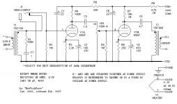
Hey Im building one of NYD's 6SN7 One Bottle mic pres. I bread boarded it and
it is awesome!!! Then I made a turret board for it. Wired up another one, enclosed it. Fired it up. And began to debug.
Here's my issue. The 1uF cap between the stages used for coupling has DC voltage present before the next stage headed to the 100K pot. Its about 11vdc. One might think okay replace the leaky cap. Well I did and it's still there. I assure you I checked that turrets connections and it only has the cap, and the lead to the pot!! ???????
My breadboarded version has no DC after this cap. So I used that one in my build and sure enough still 11VDC.
Anybody got any thoughts on this?
Attachments
You haven't built what you think you have built, or you have a faulty component.
As you have tried changing the cap, try changing the pot or the turret. Check what the other end of the pot is connected to: ground or a cathode?
As you have tried changing the cap, try changing the pot or the turret. Check what the other end of the pot is connected to: ground or a cathode?
You haven't built what you think you have built, or you have a faulty component.
Agreed. It sounds as though the grounded end of the pot is internally open circuit or goes somewhere else. If it was o/c though, the 1M resistor should ensure a good zero volts. So perhaps it's more likely that you think they're connected to ground when they are in fact connected to another point, such as the cathode of the second valve.
Well I just went cap to pot and it's fine the turret measures 11VDC just sitting on the board with nothing attached!!!!!???????
My breadboarded version has about 5 more db gain when using the same tube in both units (swapping). The breadboarded version is the exact schematic. The enclosed turreted version has a phase switch post OT. The voltages are are about 10VDC difference at all Test Points. Is the extra wiring lowering the gain or just component tolerance differences?
The plus is that the turreted version is a bit quieter than the BB'ed version.
Another question is how to arrange the neg feedback to give me -5db in one position and -10db in the other position with On-OFF-On switch. Off being no negative feed back.
Thanks for all the help.
Can't understand why that turret is measuring 11 vdc with free standing on the Board😕
Reverse-engineer your circuit from what you have built. Don't refer to the original diagram when doing this. Show us the result, unless you spot the mistake yourself.
We can't diagnose a fault from a diagram of something different (e.g. phase switch - anything else). 10-11VDC difference suggests a wiring error.
We can't diagnose a fault from a diagram of something different (e.g. phase switch - anything else). 10-11VDC difference suggests a wiring error.
Sorry I posted reply but it hasn't shown up so here goes the quick reply:
Its working Fine if I just don't use that turret. It is sitting on the board all by itself with No Connections to anything, which I checked with Continuity, measuring 11VDC. Parasitic??
I am wondering if the component value tolerance differences are to blame since my Test points are about 10VDC lower in all the B+ areas. I will check all component values and see if I can raise the voltage a little and get back my 5db that I miss so Much!
I am also wondering how to implement Feedback to get -5db, and -10db attenuation. I get the switching just not the component values to achieve this.
HA! I gave up on that turret and just removed it and went point to point cap to pot. Problem solved!
Now in regards to the output db drop. ROOKIE mistake. Edcor Swithched the primary and secondary on my transformer choice. I was using a 10k/600 on the breadboarded version and the new xfmr is a 600/10K. I wired them the same! Thats what I get for crying wolf as it were. Thanks so much. Now on to that NF implementation!!!!!
Now in regards to the output db drop. ROOKIE mistake. Edcor Swithched the primary and secondary on my transformer choice. I was using a 10k/600 on the breadboarded version and the new xfmr is a 600/10K. I wired them the same! Thats what I get for crying wolf as it were. Thanks so much. Now on to that NF implementation!!!!!
Regarding surface leakage:
Does Pencil Lead/Carbon conduct?
There was a bit of residue from when I was drilling the board material.
Maybe?????
Does Pencil Lead/Carbon conduct?
There was a bit of residue from when I was drilling the board material.
Maybe?????
Regarding surface leakage:
Does Pencil Lead/Carbon conduct?
There was a bit of residue from when I was drilling the board material.
Maybe?????
that'll do it...
Legend has it that during WW2, Forces wireless sets that suffered a burned out or broken resistor were repaired using pencil lead on paper to fabricate a replacement resistor.
Good "stick-to-it-tiveness" Goldstache!
I happened to be reading another thread, another member had a similar problem with the Edcor wires on his Power transformer primary! The lead-wires were not connected per the color-code and had to be sorted out the hard way (many, many blown fuses).
http://www.diyaudio.com/forums/tubelab/230773-basic-questions-configuring-tube-amp-7.html
Sounds like in general it would be a good thing to check the wires on a new pre-wired transformer to make sure the colored wires actually hook up the way the documentation says!!
It's always obvious after the fact, of course...
And even the "old hands" make the occasional "rookie mistake" 😀 As a good friend of mine was so fond of saying, " There ain't nothin' so simple you can't screw it up!" 🙄
I'm just starting my buildup and will check the power transformer wires on the Hammond PT I'm using. I'm still a few weeks from getting my Edcor OPTs, but those are the cheaper non-bellcap versions with solder tabs so if I screw that up I own the fault 🙂
Best luck on your amp checkout, Goldstache! BTW - the video was very cool! Thank you for posting your work! 😎
~ Sam
And yes, pencil lead will conduct. The following numbers are all very rough and approximate, just a quick Ohms Law exercise, but that could well have been your problem with that turret.
If you had 120V on the preamp plate, and about a megohm of resistance across the cap, you would get about a 10:1 voltage divider which would put around 11V on the top pin of your pot.
Current would be about 0.11mA, which might not be enough to blow out the pencil lead trace - the pencil-trace would be dissipating about 10mW, so that could well have been your leakage path.
Now, I'm wondering how conductive a sharpie would have been... 😎
Pencil lead and carbon composition resistors are similar stuff, although with different proportions and purposes. Both are carbon with a binder.
In high school auto shop class, lead pencil traces inside a distributer cap were successfully used to frustrate the shop teacher. 
Thanks for all the insight and help!
Still having some output issues with the turreted unit.
Still missing some db's and the volume is all the way up. Nowhere near where the breadboarded version sounded.
Also, when the turreted version is all the way up the unit is very microphonic. Infinitely more than the perfect performing breadboard.
I have troubleshot all the peripheral functions. Like -20db pad, phase, in xfmr and out xfmr, all jacks and connectors.
So Im looking at the circuit/turret board as the culprit.
Wondered if I could borrow you eyes and minds!
Take a peak at my layout of the board and see if you spot my error please.
The board is for the schematic at the top of this thread!
Attachments
Also, the 4.7uF cap is going to the OT not phase switch.
Also wanted to note that all voltages are on spec.
Also wanted to note that all voltages are on spec.
You say all voltages are on spec. You are describing DC voltages I presume.
Put an AC signal on the circuit and compare AC voltages to that of the breadboard unit. That should locate the gain problem.
You have two bypassed cathode resistors. Check those. They increase gain by reducing negative feedback.
Put an AC signal on the circuit and compare AC voltages to that of the breadboard unit. That should locate the gain problem.
You have two bypassed cathode resistors. Check those. They increase gain by reducing negative feedback.
Last edited:
- Status
- Not open for further replies.
- Home
- Amplifiers
- Tubes / Valves
- Strange problem with Caps not blocking DC