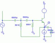
I've now reached the point where I am about to throw this circuit across the room, so I thought it might be healthier to seek some input here.
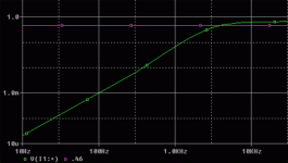
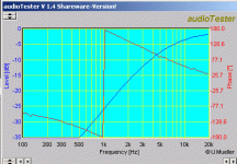
Quite simply, my problem is that the circuit below does not meet the calculated or simulated -3dB point. It should be an excruciatingly simple 12dB HP filter (ignore the passive piece as it is not in circuit) with a -3dB point around 3800Hz. Instead, the actual circuit has a -3dB closer to 7500Hz, and that is being generous about where the 0dB point is measured.
Can anyone offer any insight as to what could possibly be going wrong? I just can't fathom how this behavior could be happening.
The transistor is BC549A biased at ~1.3mA. The current source is a conventional type and is tested working.
Attachments
I dunno, bub.........
I built one, and it works. If the 6.8K resistor was missing, you might get something similar. But the slope of the response shows that it is in, and also suggests a slower transition from probably more damping. All of which suggest that some values are off.
I plugged the numbers in as if you had the frequency coefficient upside down, and that does not explain it either.
Hope your eyes aren't as bad as mine. Although that would be an acceptable excuse.
Jocko
It might help if you put some bias on that transistor, or pull the current source down to a negative rail.
I assumed that the CCS goes to the negative rail, as that is how mine was done. Hard for it to work if it wasn't.
Jocko
Jocko
If the eq. doesn't work, maybe the model is wrong
BC546's effective input impedance is too low in this circuit for it to operate as predicted. I swapped the buffer BJTs for JFETs and it works great. Anyone have an opinion on a good BJT for this application?
Thanks for the responses. They helped me keep my sanity at least. 😉
BC546's effective input impedance is too low in this circuit for it to operate as predicted. I swapped the buffer BJTs for JFETs and it works great. Anyone have an opinion on a good BJT for this application?
Thanks for the responses. They helped me keep my sanity at least. 😉
I used 2SC2240s. You expected a different answer??????
That will teach you not to use those cheap surplus parts you have sitting around.
Jocko
That will teach you not to use those cheap surplus parts you have sitting around.
Jocko
I was supposed to....but obviously not.
I am cleaning off my bench today so that I can do some other work. So maybe soon.............
You know it has to be a mess if I think it needs to be cleaned off.
Jocko
I am cleaning off my bench today so that I can do some other work. So maybe soon.............
You know it has to be a mess if I think it needs to be cleaned off.
Jocko
- Status
- Not open for further replies.
- Home
- Amplifiers
- Solid State
- Strange problem with BJT HP filter


