Hello,
I have restored an old Mc Intosh integrated amplifier MA6100, works fine.
I saw something quite strange in the PSU :


I don't understand why they make high tension (110 VCC), then drop about 100 V in R400 (3,6 k / 10 W) to finally have 10 V 😕 ... Making 12 VCA and then regulate it to have 10 V was possible and less expensive, and with no big hot running resistor !
What is the adventage of making such a power supply ?
Note : 110 VCC only goes to amplifier, no others circuits use this tension...
Thanks for your help 🙂
Please apologize for my english, I'm French 😉
Edit :... humm is it because it was less expensive to make a symetrical double secondary 2 x 150 VAC than 1 x 150 VAC and 12 VAC... ???
I have restored an old Mc Intosh integrated amplifier MA6100, works fine.
I saw something quite strange in the PSU :
I don't understand why they make high tension (110 VCC), then drop about 100 V in R400 (3,6 k / 10 W) to finally have 10 V 😕 ... Making 12 VCA and then regulate it to have 10 V was possible and less expensive, and with no big hot running resistor !
What is the adventage of making such a power supply ?
Note : 110 VCC only goes to amplifier, no others circuits use this tension...
Thanks for your help 🙂
Please apologize for my english, I'm French 😉
Edit :... humm is it because it was less expensive to make a symetrical double secondary 2 x 150 VAC than 1 x 150 VAC and 12 VAC... ???
Last edited:
Hi PRR,
Ouuuppps...
You are right : it's a very unconventional draw !
But my question is still there : why do they make 110 VCC ? In R405, more than 100 VCC are dropted. In the PSU R314 drops 45 VCC.
So there are three power resistors (on is a 10 W !), only to drop tension from the transformer ; this is quite strange... I don't think it's a very well fitted transformer ; maybe it was used in older McIntosh devices and they decided to use it as this...
Almost any resistor under a BJT long-tail pair will give "good" common-mode rejection. But for very best performance we need resistor much-much-much more than emitter resistance 're'. At 1.8mA per side, re is about 15 Ohms, so for 60dB CMRR we need 15k and 54V supply. That seems ample to me, but apparently somebody wanted "more".
Very soon after that, the price of transistors fell enough to make a transistor tail affordable. However a transistor is a less ideal device than a resistor.
Also Mac was never about cost reduction.
Very soon after that, the price of transistors fell enough to make a transistor tail affordable. However a transistor is a less ideal device than a resistor.
Also Mac was never about cost reduction.
Hello PRR,
Yes you're right, I found 66,8 dB with Mc Intosh values.
In fact on the board R409/410 is 10 kOhms
I'm quite shure it's a transformer designed for tube pre-amplifier, see the 6,3 VAC secondary winding... So they have to use the hight tension...
Yes you're right, I found 66,8 dB with Mc Intosh values.
In fact on the board R409/410 is 10 kOhms
I'm quite shure it's a transformer designed for tube pre-amplifier, see the 6,3 VAC secondary winding... So they have to use the hight tension...
Those 110V, smoothed but not regulated, are used through resistors as current sources, which start-up and shut down smoothly, and provide average current proportional to the unregulated +/-42V.
LTSpice simulation for ma6100 power output
I agree with the comments below about the 110 volt supply. I am repairing a blown output channel in a friend's ma6100 and have just finished a simulation to help me wrap my head around the circuitry in preparation. The .asc file is attached, along with a screen cap of the schematic. I'll be happy to discuss, if any interest.
I agree with the comments below about the 110 volt supply. I am repairing a blown output channel in a friend's ma6100 and have just finished a simulation to help me wrap my head around the circuitry in preparation. The .asc file is attached, along with a screen cap of the schematic. I'll be happy to discuss, if any interest.
Attachments
![2020-04-14 LTspice IV - [Mac6100.asc].png](/community/data/attachments/748/748777-b18f60807c7f64ec67f643189d15efe8.jpg?hash=sY9ggHx_ZO)
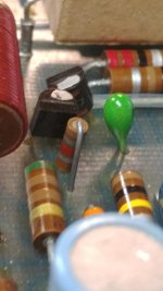
pcb input detail
The 1.8K, 1/4 watt, is on the pc board. There are also two 2-leaded TO92-size components in series with each other connected between the junction of the 1.8K and the 1.5µf cap and the input end of the 510Ω resistor. I take these to be input voltage clamps. Since I couldn't identify them I didn't put them on the schematic.
I also see 044585 silkscreened on the board, so I assume it's a later version of the 044-480. See attached photo.
Attachments
Not so strange. I had an MA6100 that needed a power supply board. Simple enough, didn't bother to create a schematic link. Everything is ceramic composition but the 5Ws. Tough to find non-inductive 5W axials that would fit on the real-estate available. Used AGX-5s to get a bit more board space. The main rectifier bridge set for either ceramic or AC pulse polyethylene.


- Home
- Amplifiers
- Power Supplies
- Strange Power Supply McIntosh MA6100