Hi tpa3116 gurus,
I’ve got a nice collection of different cheap tpa3116 boards and none of them are that different than the reference design in terms of output filtering. Except, naturally, the ones i want to use for this project.
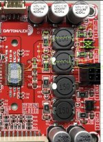
These sure/wondom/dayton boards using the tpa3116 (i have the dayton kab-1100 and the dspb-250) use a strange filter with a diode rectifier in it. I have scoured the internet to find a similar circuit and i think my amateur EE skills have reached their limit.😕
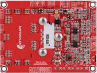
I’ve retraced the circuit to the best of my ability (some of these boards are more than 2 layers) and overlayed it on the picture. The picture here is the simplest of the boards, but they all have the same architecture.
What do you think? I’m looking to get rid of the ceramics in the signal path and potentially increase the size of the inductors (all of my other boards have 330 or 220 inductors)
Any references to how these type of filters work would be great. I want to learn as well as make these amps reach their potential.
I’ve got a nice collection of different cheap tpa3116 boards and none of them are that different than the reference design in terms of output filtering. Except, naturally, the ones i want to use for this project.
These sure/wondom/dayton boards using the tpa3116 (i have the dayton kab-1100 and the dspb-250) use a strange filter with a diode rectifier in it. I have scoured the internet to find a similar circuit and i think my amateur EE skills have reached their limit.😕
I’ve retraced the circuit to the best of my ability (some of these boards are more than 2 layers) and overlayed it on the picture. The picture here is the simplest of the boards, but they all have the same architecture.
What do you think? I’m looking to get rid of the ceramics in the signal path and potentially increase the size of the inductors (all of my other boards have 330 or 220 inductors)
Any references to how these type of filters work would be great. I want to learn as well as make these amps reach their potential.
Attachments
Where does the upper right terminal on the rectifier block go?
That will show the purpose of the rectifier. It's a full wave type
on the floating outputs, with the positive rectified output referred to ground,
so the upper right terminal has a negative FWR output voltage.
The other parts are just an output filter with snubbers, similar to figure 37 here:
https://www.ti.com/lit/ds/slos708g/...ttps%3A%2F%2Fwww.ti.com%2Fproduct%2FTPA3118D2.
Last edited:
The diode is described in one of the first posts in 3116 thread, is a no load(or very high load) protection circuit
Rayma: i’m not sure where it goes!
Irribeo, ok, i went and read that and it makes sense. So basically i can just ignore them, they aren’t hurting anything.
Which would the critical caps be then? C4 and C12? Corresponding to C51 and C52 in the reference design?
Irribeo, ok, i went and read that and it makes sense. So basically i can just ignore them, they aren’t hurting anything.
Which would the critical caps be then? C4 and C12? Corresponding to C51 and C52 in the reference design?
Attachments

Well actually they have the same artwork for mono and stereo boards, so thats just one half of the LC filter then.
Well actually they have the same artwork for mono and stereo boards, so thats just one half of the LC filter then.
The schematic shown has a mono bridged output (for twice the output voltage).
Sounds like the diode block is an output voltage clamp.
Last edited:
Which would the critical caps be then? C4 and C12? Corresponding to C51 and C52 in the reference design?
I'd say C51/C52 are the most critical ones. They're part of the LC output filter, set at around 53kHz.
The other, smaller capacitors may be, and should be, COG/NPO types, and if so are fine.
Those reduce ringing and EMI.
Last edited:
c4 c12 c19 c30 are the main filtercaps and those matter a little, but you probably have other 3116 ampboards that sound ok with similar ceramic filtersmd's
What is specifically your complaint with the quality ?
What is specifically your complaint with the quality ?
Actually all my good sounding boards have at least one film cap in the output filter. I can’t put my finger on what makes these sound bad. Seems like some distortion even at low volumes. I’m putting together a setup to measure thd and hopefully there will be some telltale signatures. I’m also going to measure a ‘good’ sounding one. I lack the vocabulary to describe noise without looking at a spectrum or something, unfortunately.
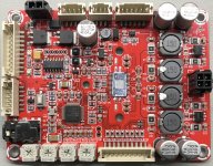
The fact that the mono and the stereo have the same filters (even values for inductors) is a bit of a red flag for me. None of my others are like that. Maybe no scientific reason but i’ve got to research that a bit i guess
The fact that the mono and the stereo have the same filters (even values for inductors) is a bit of a red flag for me. None of my others are like that. Maybe no scientific reason but i’ve got to research that a bit i guess
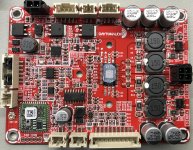
The only part of the board I wonder about is the groundplane under the inductors that is separated, maybe that makes returnpath longer for the filtercurrents, longer is inductive, is bad here, but I only wonder.
Mono being parallel btl makes the same filter more normal, but mono pbtl requires one input to be grounded, is it?
Mono being parallel btl makes the same filter more normal, but mono pbtl requires one input to be grounded, is it?

Weird I assumed these were identical but the Sure?Wondom seems quite different, topside seems the same though

Is the Dayton much cheaper than the $34,90 price of the Sure?
Yes, it is grounded just like the reference design.
I’m wondering if they are using a ‘hybrid’ filter design as discussed here 404 Not Found
https://www.eetimes.com/understanding-output-filters-for-class-d-amplifiers/?page_number=1
I’m wondering if they are using a ‘hybrid’ filter design as discussed here 404 Not Found
https://www.eetimes.com/understanding-output-filters-for-class-d-amplifiers/?page_number=1
Attachments
Last edited:
How do i diagnose what is limiting in the output filter? I’m tempted to see if i can just jumper over to another board’s output filtering to do a comparison. But what would i be looking at? some telltale frequencies in the fft or is there a way to measure the filter response using the REW soundcard analysis rig...?
It's a simple LC low pass filter, much depends on implementation and board layout.
Jumpering the raw outputs to another board may be self-defeating.
Jumpering the raw outputs to another board may be self-defeating.
- Home
- Amplifiers
- Class D
- Strange output filter on Dayton/sure/wondom tpa3116 board