For a vertical array the horizontal directivity is equivalent to that of a single driver. Hard to say if that is GOOD or BAD.
David
Exactly, but as the wonderful thing about CBT arrays is the constant directivity it's kinda sad that it doesn't apply to the horizontal axis.
Its a passive crossover, in a way. Why is that a problem?Don't you have any concern about adding all the extra components to the signal path?
Exactly, but as the wonderful thing about CBT arrays is the constant directivity it's kinda sad that it doesn't apply to the horizontal axis.
In the pro world they tend to create modules with CD in the horizontal plane (say 90 degrees), then design the array for whatever vertical pattern they want.
Also, nothing stops you from making a 2d array, that is an array with rows and columns of speakers. If you needed both narrow horizontal and narrow vertical then that would be your only approach.
David S.
Don't you have any concern about adding all the extra components to the signal path?
If that is something you loose sleep over, then these are not for you.
Still, wouldn't the wonderful improvement in directivity control and the ability to make the floor bounce disappear be a nice trade off against the hypothetical (and unmeasurable) ills of passive components?
David
Also, nothing stops you from making a 2d array,
David S.
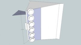
I plan to put the array on a 90 degree waveguide. Not exactly same as the attached image but quite similar.
The reason why I think the waveguide will work is that I have drivers that are really small. They are 19mm drivers with a very small 9mm round exit (typically used in cellphones).
Attachments
Still, wouldn't the wonderful improvement in directivity control and the ability to make the floor bounce disappear be a nice trade off against the hypothetical (and unmeasurable) ills of passive components?
David
David, Thanks for confirming that the tradeoff works.
In the pro world they tend to create modules with CD in the horizontal plane (say 90 degrees), then design the array for whatever vertical pattern they want.
Also, nothing stops you from making a 2d array, that is an array with rows and columns of speakers. If you needed both narrow horizontal and narrow vertical then that would be your only approach.
David S.
Yup, my dipole-idea is to make a smaller one: say 34 cm in diameter but make it the whole spherical cap instead of a line.
As CD in the bass region is easy with a dipole it would be enough to let it handle say 500 hz and upwards. And the CBT property will only need to start at about 1 khz as the dipole arrangement will handle CD below that. It would need some active DSP prototyping first though to find out the slopes of everything, doing that passively form the start would just be economical suicide =)
How should I use the mids?
The mids will be bolted to the waveguide wall and radiate via ports in the wall. So, my next question is how should I use the mids?
1) By tuning the mids as a 2 octave bandpass from 300hz to 1200hz, I expect the port dia to be about 10mm.
2) Or use them as fullrange starting from the mid's Fs (about 250hz to over 1200hz). The port is oversized (about 25mm) to allow the mid driver to run as a fullrange rather than a bandpass
The array is about 20" tall and the number of mids are about 12 per array (6 in each waveguide wall).
Thanks,
Goldy
Does driver impedance matter
The JBL CBT-50 that I am trying to base my design on is a 8 ohm impedance unit. Does it mean all the drivers are 8 ohms?
If that is the case, does it matter whether I use 4 ohm drivers or 8 ohm drivers? I am only asking this from the point of view of interaction between the driver impedance and the LC ladder using the component values of JBL CBT50. Its a given that I will level match the tweeter array and mid array. Each line will have independent amp.
I have many doubts, and need help before I proceed with the build
Thanks,
Goldy
It would matter what the driver impedance is but you can scale their network if your driver is 4 instead of 8. Since that is half impedance then cut all network impedances in half. That means double every capacitor value and halve every inductor.
David
David
It would matter what the driver impedance is but you can scale their network if your driver is 4 instead of 8.
David
Hi David,
The LC pair are used to emulate the circulate arc (delay). So it means the LC values cant be changed without affecting the arc. Is my understanding correct? Also I don't see the load value being taken into consideration in the patent.
Thanks,
Goldy
Hi David,
The LC pair are used to emulate the circulate arc (delay). So it means the LC values cant be changed without affecting the arc. Is my understanding correct? Also I don't see the load value being taken into consideration in the patent.
Thanks,
Goldy
Keep in mind that it's not the component values that create the phase delays but the acoustical responses. Unless the drivers you choose have exactly the same impedance response as the ones in the paper you'll probably have to calculate your own values.
In the end it is the relative delay between the elements. That means that the system is scalable in impedance and immune from the particular response of the elements (presuming all elements are the same).
Scaling impedance the way I mentioned (cutting all reactances in half to match a 4 ohm rather than 8 ohm) would give the same electrical curve shape at the terminals of each driver. That would give the same phase shift or group delay and so should match well to the JBL design.
If your driver response is way different than the JBL target, you should still use the same network (scaled or otherwise) to create the array, then use global EQ in front of the whole array.
Regards,
David
Do mids really need the LC network?
The intended array is about 20" tall and will lose vertical pattern control at a frequency where the height of the array is twice the wavelength. The below is a quote from Don Keele's CBT AES paper (Application of Broadband Constant Beamwidth Transducer (CBT) Theory to Loudspeaker Arrays). In the paper he describes an array 27" high losing pattern control as quoted below
"The height is two wavelengths at 1 kHz. This provides beamwidth control down to
approximately 1 kHz".
So my 20" array is going to loose pattern control by 1350hz (and below). The mids wont have much pattern control anyway.This fact can be used to avoid the LC network completely for the mids. Probably the mid array would just work fine with plain shading to attenuate the top and bottom drivers.
Any thoughts?
I have designed units with plain shading and gotten good results. We also know that the CBT approach works very well. I'm not sure I would try and mix the two.
It sounds like you want to create a 2 way array (2 arrays crossed over). If that is the case the ideal approach is to fully scale between two arrays. That is have a short upper range array and, say, a 3 times as long array of larger drivers with all crossover network components scaled down in frequency to suit.
Your problem will be that, if you don't copy this design pretty closely, you will have to go off in your own direction and design from scratch. That wouldn't bother me because I have the design tools to do it, but do you?
Note that your array loses pattern control at low frequencies from lack of length. The phase shift, from end to end becomes too small to give LF directivity. This will generally be true no matter what approach you want to use (CBT or shading).
David
I figured out some things
1)The "mistuned" (part in the patent) means that the low pass corner freq is set for delay and not for a particular cutoff.
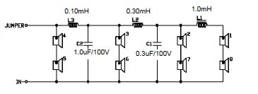
Look at the first two LC sections of CBT-50(image with 4 stages), it has each LC section fixed at 16khz when viewed as a typical low pass.
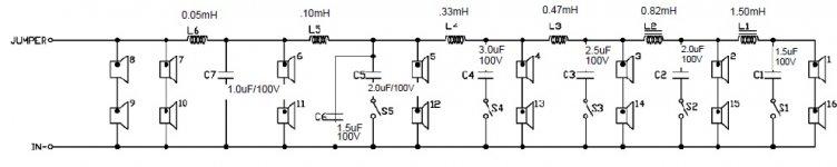
2)But look at first two LC sections of CBT-100 (image with 7 stages), it has the first LC at 22.5Khz and the second LC section at 8.5 khz
3) If we use the CBT-50 or CBT-100 driver arrangement, then at lowest frequency (where L is closed and C is open), the array impedance is such that as if all the stages were in series-parallel. So the drivers are choosen with unusually high impedance (about 10 ohms in case of CBT-50)to yield a nominal 8 ohm array impedance.
4)The delay also seems to be independent of the load resistance. LC ladder networks create delays at each stage equal to the root of LC product at that stage.
1)The "mistuned" (part in the patent) means that the low pass corner freq is set for delay and not for a particular cutoff.
Look at the first two LC sections of CBT-50(image with 4 stages), it has each LC section fixed at 16khz when viewed as a typical low pass.
2)But look at first two LC sections of CBT-100 (image with 7 stages), it has the first LC at 22.5Khz and the second LC section at 8.5 khz
3) If we use the CBT-50 or CBT-100 driver arrangement, then at lowest frequency (where L is closed and C is open), the array impedance is such that as if all the stages were in series-parallel. So the drivers are choosen with unusually high impedance (about 10 ohms in case of CBT-50)to yield a nominal 8 ohm array impedance.
4)The delay also seems to be independent of the load resistance. LC ladder networks create delays at each stage equal to the root of LC product at that stage.
Attachments
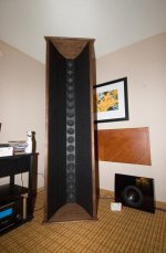
Goldy pointed me towards this topic, and i reverse-simulated JBL CBT50, knowing that it is a sleek column of eight 2-inch drivers, and the circuit posted by Goldie, which makes sense only, if 4 Ohms drivers are used. So there is a 2:1 transformer used, in order to obtain 8 Ohms for the full box. Compared to a simple line array, comb-filtering and spatial aliasing peaks are much reduced. There is much beaming, but beamwidth is not anywhere near constant. It is prolly more constant in CBT100 in "wide" setting.
Attachments


Hello @goldyrathore,
I would be interested in knowing the status of your work on CBT. Any interesting progress?
Thanks,
Manuele
I would be interested in knowing the status of your work on CBT. Any interesting progress?
Thanks,
Manuele
- Home
- Loudspeakers
- Multi-Way
- Straight Line CBT array