Hey all,
As far as inrush current from SMPS to cap bank harming the SMPS, can you put in a resistor based Soft Start circuit between the SMPS and cap bank to ramp up the charging of the caps?
I have a simple DIY Babo Zen (a modified Zen V5 with jfet inputs - essentially an simple Pass F5) powered with four 96 watt Laptop SMPS for +/-18VDC and it sounds great - but always wanted to put a cap bank between them to see if any more improvement would be found - just always worried about destroying the laptop power supplies - not a big deal as they were $10 each shipped from China...and considered the soft start board....
Hey all,
As far as inrush current from SMPS to cap bank harming the SMPS, can you put in a resistor based Soft Start circuit between the SMPS and cap bank to ramp up the charging of the caps?
Yes you could, BUT since it is a high frequency SMPS not a low (line) frequency linear, the ideal cap bank is not one with high farad value, it's one with especially low impedance. SMPS impedance is already more of a limit so IMO for any real improvement it wouldn't be necessary.
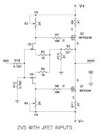
I have a simple DIY Babo Zen (a modified Zen V5 with jfet inputs - essentially an simple Pass F5)
A Zen v5 already has an overkill amount of capacitance that already puts a strain on your PSU if built as most commonly spec'd.
powered with four 96 watt Laptop SMPS for +/-18VDC and it sounds great - but always wanted to put a cap bank between them to see if any more improvement would be found - just always worried about destroying the laptop power supplies - not a big deal as they were $10 each shipped from China...and considered the soft start board....
"Improvement" is a relative and even more so, subjective term in audio. We can't know what you like the sound of best. If you are not content then keep fiddling till you get tired of fiddling and are content. 😉
SMPSUs are designed with current limiting so I can't see that adding caps to the output is going to damage them. After all they already have some output capacitance internally so always start up into an apparent short. I would suggest a series inductor prior to the extra caps for HF noise reduction.
A Zen v5 already has an overkill amount of capacitance that already puts a strain on your PSU if built as most commonly spec'd.
Actually, no caps, at all - attached circuit with two laptop power supplies wired 18 - 0- -18 to each amp rail...
Note = Papa corrected the schematic...
"correction:
set R10 = 1K or so
R12 = 47K or so"
Attachments
Last edited:
Actually, no caps, at all - attached circuit with two laptop power supplies wired 18 - 0- -18 to each amp rail...
Note = Papa corrected the schematic...
"correction:
set R10 = 1K or so
R12 = 47K or so"
Oh, then doesn't it deviate from most commonly spec'd which is with at least 10,000 uF or higher caps right there on the amp board?
I would put a minimum of 470uF to 1000uF low ESR caps on each power rail to ground, per channel physically close to the Q1 & A2 pins, but leaving enough space to fit 1uF film caps in parallel right next to the Q pins.
Even if the PSU didn't have current limiting that is a lower capacitive load than a typical laptop would present.
The expected result would be a less lively amp, smoother with reduced errors and possibly tighter bass IF you can hear any difference. It still depends on your ears if that is an improvement or not.
SMPSUs are designed with current limiting so I can't see that adding caps to the output is going to damage them. After all they already have some output capacitance internally so always start up into an apparent short. I would suggest a series inductor prior to the extra caps for HF noise reduction.
good SMPS supplies have feedback loops. SMPS design balances ripple reduction and stability. with modified output LC filters changes to loop gain /phase margins get worse. arbitrarily adding 1000% or more C on the output.... well multiple folks that have SMPS design experience have already warned against it in the thread. anyway the baseline target for switching noise is less than most unregulated linear designs at 120Hz which really need those big honking Caps. I typically see common mode noise being the issue that raises its ugly head these SMPS audio apps. your added series L outside loop is a good thought tho. I'd use CM chokes in conjunction with local amp decoupling instead. repeat without SMPS V feedback. etc
the output Capacitor/s selection is critical design aspect of SMPS, ESR at high frequencies etc. there are many tradeoffs built in there.
EDIT I think you guys need to build it 1st
wire up an audio PA using a SMPS with V regulation, do some square testing , overdriven to rails etc. then start adding big Caps and see what happens, ie not much improvement to amp at the expense of potential PS instability.
Last edited:
good SMPS supplies have..
How about cheap smps supplies? In the venerable EL Cheapo challenge traditions of DIYAudio I thought I would revive this thread after finding and buying one of these $11 smps's
High Voltage DC DC Boost Converter 8 32V to 45V 390V ZVS Capacitor Charging free shipping -in Integrated Circuits from Electronic Components & Supplies on Aliexpress.com | Alibaba Group
Can a reasonably clean high voltage supply be made with this board as the basis? Say for 200- 250VDC 50ma or so out?
I am simply not knowledgeable enough with solid state electronics, let alone smpses to offer much to start with, though a capacitor multiplier come to mind. With 12Vs in it seems to be able to produce a steady 250vdc with a fun 4vac. Supposedly it switches at 75K.
Any thoughts?
test it with dummy load >watch for turn on /off behavior on an O- scope
the outputs are dual with grounding at center so it maybe unhappy with no loading on one side.
probably best results with floating DC input and using load across both outputs. IMO aint this a supply to plug n play for audio stuff, no not without SMPS knowledge on filters and grounding ,and hanging big ole cap is rarely a solution in this. is 4 volt AC RMS ripple on a scope?
take an image of the control circuitry on bottom side and study the data sheet for better clues!
might use a series power resistor and smallish decoupling cap across the output load , to limit max power to less than 40W this will prevent damage at the expense of efficiency. note its RC time constant.
Last edited:
>is 4 volt AC RMS ripple on a scope?
no voltmeter.
>hanging big ole cap is rarely a solution in this.
How do you define a big cap?
I was able to get it inaudibly quiet using 2 10uf, TIP50 based capacitance multipliers one feeding the next followed by a .1uf to ground. I have not left it on for very long. Is this to much capacitance?
no voltmeter.
>hanging big ole cap is rarely a solution in this.
How do you define a big cap?
I was able to get it inaudibly quiet using 2 10uf, TIP50 based capacitance multipliers one feeding the next followed by a .1uf to ground. I have not left it on for very long. Is this to much capacitance?
the outputs are dual with grounding at center so it maybe unhappy with no loading on one side.
there is also a single output version for less than 7 $; picture and part of the description shows dual, but it is actually single:
High Voltage DC DC Boost Converter 45V 390V 110V/220V ZVS Capacitor Charging Single Output Boost Module SG128 SZ+-in Inverters & Converters from Electrical Equipment & Supplies on Aliexpress.com | Alibaba Group
Here are couple more from eBay; 70W and 150W! Given how small and cheap they are, I cant believe they aren't worth exploring for tube audio projects, for prototyping if nothing else.
DC12V 24 to DC 200 450V 70W High Voltage Converter Boost Step Up Power Supply | eBay
12V to DC450V 150W High Voltage Converter Boost Step Up Power Capacitance Charge | eBay
DC12V 24 to DC 200 450V 70W High Voltage Converter Boost Step Up Power Supply | eBay
12V to DC450V 150W High Voltage Converter Boost Step Up Power Capacitance Charge | eBay
I requested schematics or better photos for more comments
ZVS is the interesting feature, is it?
here is the single output version http://www.aliexpress.com/item/High...nverter-Step-Up-Boost-Module/32309832793.html
note> missing cap and diode > output power is the same so that gives hope no ill effects from operating 1/2 of the dual version
capacitor multiplier is a solution for linear supplies, any ripple reduction is either accidental or from device / wiring parasitics. without a scope and schematic were stumbling around.
Last edited:
Good find! That does look more appropriate. The little testing I have done on the dual supply version was using the + and - outputs and not + and ground.
The vendor would not supply a schematic for dual supply board and most of the chips have had their information removed. The photos in the version you have found are better than what I can post.
You comment on the capacitance multiplier is very interesting. Can you please explain a little more why one wont work after an smps?
BTW apologies, the 4vac was way off, bad measurement of some kind. Its .1vac rms and .01 after the mulitplier. It may be the result of wire parasitics as you say, but it is definitely not an accident.
Also can you give some kind of ball parks as to how much capacitance is to much after a supply board like this? 1uf, 10, 100, 1000 or is it dependent on the circuit?
If these questions are to broad or uniformed for you, no problem, thanks for your comments so far.
please check the specs of your DMM for AC measurements. I expect ripple to be a multiple/s of the switching freq and def. not sinusoidal.
cap multipliers are usually reserved for cleaning up voltage references where ripple is predominantly related to power line frequencies and used in other places it usually wrecks transient response / regulation and eff. at higher current power apps. IDK A simple series power resistor and/ or lossy inductor followed by a low esr cap may work better for your HV SMPS and provide some output current limit protections. Consider common mode chokes on both input and outputs with decoupling caps working these higher frequencies.
sorry I really don't much about your application E.g. the load , the 12V source, and grounding or any of the SMPS details. it usually pays to test the power supply alone for in/out regulation, overshoot etc. before slapping it into a circuit.
cap multipliers are usually reserved for cleaning up voltage references where ripple is predominantly related to power line frequencies and used in other places it usually wrecks transient response / regulation and eff. at higher current power apps. IDK A simple series power resistor and/ or lossy inductor followed by a low esr cap may work better for your HV SMPS and provide some output current limit protections. Consider common mode chokes on both input and outputs with decoupling caps working these higher frequencies.
ripple reduction is the ratio of series R+L and shunt esr at the frequencies of interest> remeber this isn't 120Hz so arbitrarily big C values don't work well at SMPS frequencies. so in general look for narrow lead spaced caps designed for SMPS (low esr.) also ceramic caps work best for hash and noise ~ 1-10's of uF in parallel with 0.01uF. IMO high voltage makes cap selection orders more difficultAlso can you give some kind of ball parks as to how much capacitance is to much after a supply board like this? 1uf, 10, 100, 1000 or is it dependent on the circuit?
sorry I really don't much about your application E.g. the load , the 12V source, and grounding or any of the SMPS details. it usually pays to test the power supply alone for in/out regulation, overshoot etc. before slapping it into a circuit.
Last edited:
They look identical to me. I think you found a lower price vendor.
nope, single output, picture and part of the description is wrong, no negative out - hence the lower price ...
confirmed by a french buyer's comment:
" bien mais attention à la description...une seule sortie .. photo et description generale fausse pas de sortie negative "
But what puzzles me about the +/- output version:
- how can a non-isolated boost converter produce both, a positive AND a negative voltage ?
- boost has only an inductor and can only boost one polarity !
- unless it is actually a flyback with transformer secondary center tapped ...
- but then, why non-isolated ? 0v tap connected to input gnd on purpose ???
.... and be careful, I would not count on those cheapos having a bleeder on the output caps, if they stay charged and you accidentally touch + and - 700v across ... not funny ...
!!! 1st thing to add bleeder Rs !!!
Last edited:
Thanks for the bleeder advice payloadde, will do!
Infinia my immediate application is for a class a pp tube headphone amp that needs a B+ of 230v at 60ma quiescent. The appeal of an smps supply, besides cost, is the size. It would be great to have 12vdc external power supply with a long cable running to small box on my desk. So my power needs are relatively low (for tubes anyway) but I need a relatively low noise output, not ultra-low or optimally low, simply low enough that I cant hear it. : )
Do you have any suggestions for the spec of a common mode choke to try after ththis board?
What do you mean by a "lossy" inductor?
With a linear supply I would need a pretty hefty choke with a 10uf cap for a resonant frequency under 10hz. If I understand you in this case the point of the LC is to filter noise that is much higher so I can use a much small choke is that right?
Might there be an advantage to replacing the electrolytics on the board with higher quality (presumably lower esr) versions. They are all 10uf?
- Status
- Not open for further replies.
- Home
- Amplifiers
- Power Supplies
- storage caps AFTER the SMPS