Hi everyone,
I've salvaged a few parts from a Sony HCD-XB5, with a working STK4231II.
The parts I have are:
- Power Transformer
- Main Board
- Power Amp Board
- Heatsink
For now I pretend to keep the Power Amp Board and the transformer.
My objective is to make a preamp, output and protection board to use with the STK.
The features I want are:
- Relay driver circuit
- Speaker protection with power-up delay and instant relay opening at turn off
- S/C protection based on the overload detection circuit
- Speaker fuses (I know it's not a great idea but it might protect the OPS, if loads are shorted and the protection does not engage)
- Headphones output based on resistive voltage divider
- Audio preamplifier with equalizer, tone control, balance and volume control
- Microphone and line level inputs
My biggest problem now is the protection circuit, I have the protection IC, but I suspect it might be faulty. There are no replacements for this ICs that I am aware about. Any suggestions of circuits that perform similar to the uPC1237? I have looked at a few, but I need help to understand how the overload detection works.
I also don't know if the voltage divider is adequate or if it should be higher or lower.
I've attached schematic of the output circuit I've made in LTSPice.
The Sony HCD-XB5 manual is a very large file, it is available here, the main board circuit schematic is in page 54 of the PDF, and the power amp board circuit schematic is in page 58 of the PDF. The boards are interconnected via connector G.
Regards
Danny
Attachments
I honestly can't recall any case of an actual protection IC having been faulty. Associated external circuitry / parts, sure, that happens. If in doubt you could always try buying a cheap protection board using the same chip and salvage it from that. But my bets would be on something else. The last case of a faulty protection here was with a Sansui AU-X501 - the OP eventually found a bad resistor. If in doubt just test any and all parts associated with protection and relay drive.
I certainly wouldn't have both a relay and a fuse, no manufacturer does that. Some people add 10-100 nF across the relay to avoid arcing, the most common degradation mechanism next to contact tarnishing.
If you want to make a new preamp anyway, why not integrate a headphone driver / buffer with that, instead of using the primitive resistor dropper? Tap off after preamp with one or two NJM4556A followers paralleled O2-style, and Bob's your uncle. (That is assuming your preamp supply are no higher than +/-15 V, which they usually are.)
If you've got another volume pot to spare you could even include a headphone level trim. In fact, you could even use a whole O2 board as the preamp (tapping off after the gain stage, maybe at the pot), with another 10k pot in front. (Note that at 6.5X gain, I would rather swap both resistors in the gain stage feedback network for something about twice in value, so maybe 3k0/560R (3k01 / 562R). Otherwise the NJM2068 is a bit unhappy at high levels, which is not really worth the extra 0.7 dB or so less noise - it's hardly excessive as-is.)
What the whole setup will need is some careful planning of grounding, as you don't want to get any ground loops. This can happen very quickly. Ideally you'll make a plan for the whole ground routing, which should make it easy to identify any trouble spots. For example, you may want to have both inputs and output grounded to the case but there may be a ground running alongside the signal from input to output as well - or maybe there's an interruption somewhere, e.g. at power amp input.
Last edited:
Hi sgrossklass I appreciate your help,
I suspected the uPC1237 because sometimes, when the equipment was operating, the right channel relay would stay open after the initial delay at startup, it resolved after a few power cycles. Of course this may also be a problem of the relay itself, or something wrong at the output of the amp like DC presence or a S/C. Maybe it's better to get it off the board and test it.
You've sugested, if the IC is really faulty, to buy a cheap protection board with a uPC1237 or similar, but this chips are really reliable? I've heard that there are lots of counterfeit parts/fakes.
I would like to keep the headphones output from the STK, I don't know why but I like the sound from it, maybe if possible I would like to have two of them, one from the speaker amp and another for the other headphones amp.
The speaker fuse is the last line of defense on the case of relay failure, in the case of the contacts might became welded, arcing occurs, or protection circuitry fails, I know it's not a very good idea, but it generally works.
I know it might sound weird (shame on me!), but I'm not familiar with the O2, or the other type of amp you've mentioned, I will take a look.
The last HP amplifier I've made was one based on Rod Elliot's Project 113.
Regards,
Danny
Last edited:
I've followed your suggestion, and took a look at the O2 headphones amp, and seems really nice. 😀
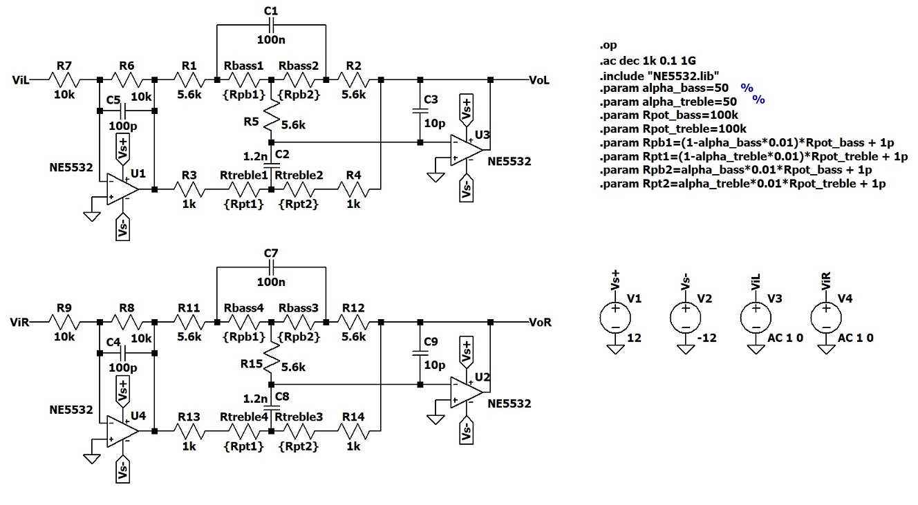
As you suggested I've changed the resistors in the feedback loop of the preamplier opamps to 3k/560.
I'm also thinking about adding balance control, tone control and/or equalization, but I don't know if it is better to place this stages after or before the preamp. After seems better from a S/N perspective, but worst if the signal clips at the preamp, unless the volume control potentiometer stays between the preamp and tone control.
LTSpice schematic and models attached.
Regards,
Danny
Attachments
Really, it depends on what these stages will be looking like in terms of impedance and parts. The best place might be at line level ahead of all of this preamp and volume control stuff - levels tend to be high enough there for you to get away with typical circuitry (e.g. Baxandall with 50k or 100k pots and 5532) without inducing undue noise, but at the same time don't tend to exceed about 2 Vrms much, so you retain some headroom for tone adjustments.I'm also thinking about adding balance control, tone control and/or equalization, but I don't know if it is better to place this stages after or before the preamp. After seems better from a S/N perspective, but worst if the signal clips at the preamp, unless the volume control potentiometer stays between the preamp and tone control.
As for your schematic, I would probably prefer tapping off the power amp ahead of one of the 1 ohm combining resistors, with maybe 100 ohms in series, and placing the second pot after that. About 2k5 of source impedance seems low enough to feed a power amp even without input bootstrapping at the latter, but adding some may be beneficial nonetheless.
Last edited:
Thanks for your repply sgrossklass, I appreciate your help 🙂
The PA has a gain of about 37.7 dB which is a lot, I think 2 Vrms can be too much. Maybe about 1 Vrms or a bit less is sufficient.
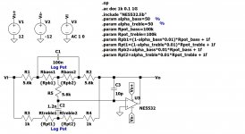
Draft of the tone control circuit attached (one channel only). I don't know why, but I'm not being able to simulate the circuit properly in LTSpice, it is giving me wrong gain values when I adjust the treble pot. 🙁
If the power amp input is connected to the same place of the headphones, HP loading variations might affect the input amplitude of the PA, if both HP and PA amps are operated at the same time. Right? 😕
Sorry about my ignorance 😛, what is input bootstrapping?
Which are the main benefits and drawbacks (if any) of an O2 like HP amp, when compared to an opamp with a simple class AB output driver, made out of resistors, caps, bias diodes and a BJT complementary pair, or a darlington pair?
Regards,
Danny
Really, it depends on what these stages will be looking like in terms of impedance and parts. The best place might be at line level ahead of all of this preamp and volume control stuff - levels tend to be high enough there for you to get away with typical circuitry (e.g. Baxandall with 50k or 100k pots and 5532) without inducing undue noise, but at the same time don't tend to exceed about 2 Vrms much, so you retain some headroom for tone adjustments.
The PA has a gain of about 37.7 dB which is a lot, I think 2 Vrms can be too much. Maybe about 1 Vrms or a bit less is sufficient.
Draft of the tone control circuit attached (one channel only). I don't know why, but I'm not being able to simulate the circuit properly in LTSpice, it is giving me wrong gain values when I adjust the treble pot. 🙁
As for your schematic, I would probably prefer tapping off the power amp ahead of one of the 1 ohm combining resistors, with maybe 100 ohms in series, and placing the second pot after that. About 2k5 of source impedance seems low enough to feed a power amp even without input bootstrapping at the latter, but adding some may be beneficial nonetheless.
If the power amp input is connected to the same place of the headphones, HP loading variations might affect the input amplitude of the PA, if both HP and PA amps are operated at the same time. Right? 😕
Sorry about my ignorance 😛, what is input bootstrapping?
Which are the main benefits and drawbacks (if any) of an O2 like HP amp, when compared to an opamp with a simple class AB output driver, made out of resistors, caps, bias diodes and a BJT complementary pair, or a darlington pair?
Regards,
Danny
Attachments
I was referring to levels ahead of the preamp.The PA has a gain of about 37.7 dB which is a lot, I think 2 Vrms can be too much. Maybe about 1 Vrms or a bit less is sufficient.
But if you have that much power amp gain (any clue about the feedback network resistors?), I might consider reducing preamp gain. In practice with relatively high-level sources, a gain of 2.5X (8 dB) is often found to be easily sufficient, and in fact with CD player levels (0 dBFS = 2 Vrms) and typical HiFi headphones of 102-103 dB SPL / V (Sennheiser HD600/650, Beyer DT880 etc.), people are often running unity gain. I have often argued that the 1X/2.5X gain combo actually makes more sense for most people.
8 dB would give you very typical 85-100wpc integrated amplifier gain in total (45.7 dB). That's plenty enough even for a phono stage with some room to spare. Unity gain would still give you the 37.7 dB of the power amp, still more than enough for most non-phono sources.
Hmm. I am actually fairly certain that the inverting Baxandall normally uses linear pots, that's part of its appeal. It should also be driven from a low-impedance source, so often a buffer is included. At line level, this could be something rather basic, MC33078 or LM833 or even NJM4558 or 4580 perhaps.Draft of the tone control circuit attached (one channel only). I don't know why, but I'm not being able to simulate the circuit properly in LTSpice, it is giving me wrong gain values when I adjust the treble pot. 🙁
That's why I suggested to tap off between one of the 4556 outputs and its 1 ohm combining resistors, where output impedance is super small and the effect of any loading would not show up in frequency response (only possibly in extra distortion).If the power amp input is connected to the same place of the headphones, HP loading variations might affect the input amplitude of the PA, if both HP and PA amps are operated at the same time. Right? 😕
I did make an oopsie last time and failed to consider the necessity of switching between speakers and headphones, sorry 'bout that. Maybe get a HP jack with an extra switching contact and use that to engage a 24 V relay between +/-12 V (dissipate any extra voltage via series R). 2x DPDT, maybe Au-plated contacts, nothing super huge required. Then the signal could be routed to the jack when plugged and to the speaker amp when unplugged.
That's a question possibly better answered by The Art of Electronics. The idea behind bootstrapping is that an input resistor will appear to be much larger than it actually is if the other end keeps actively tracking the input voltage. Feed in 90% of the input signal there, and the resistor will only carry 10% the current - it will appear to be 10 times as large. Likewise, the effect of input capacitance and input bias currents is similarly reduced, which can be important if the input transistors are run hot and have quite a bit of (nonlinear) input bias current that would cause substantial distortion when faced with high-impedance sources.Sorry about my ignorance 😛, what is input bootstrapping?
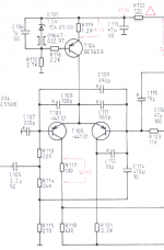
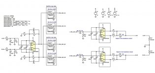
Now where do we get a suitable source for something like that? Well, try the inverting input for one. Here's a typical example, borrowed from a Grundig V5000:
R123/(C114 + R115) is the classic feedback network. R and C have been switched around for convenience / saving parts, otherwise you'd need two caps here.
R114 is the input / bootstrap resistor.
This usually costs you some gain somewhere (the usual rule of thumb for bootstrapping is "higher input impedance, higher output impedance"), but it can't be that much here.
On the plus side, you get a proven known-good circuit and particularly board layout, and you can even buy a finished board or kit. If you're a layout wizard who regularly rolls their own boards this might not matter, but not a lot of people are. Remember, the layout is the circuit.Which are the main benefits and drawbacks (if any) of an O2 like HP amp, when compared to an opamp with a simple class AB output driver, made out of resistors, caps, bias diodes and a BJT complementary pair, or a darlington pair?
The pair of 4556As was chosen because it was easy, cheap, has moderate idle current consumption (important for battery operation) and generally gets the job done well enough. Can you do something better with another opamp and a discrete buffer, especially if power is no object? Of course. Will you have to do a bunch of simulating and troubleshooting to make it work 100%? You bet you will.
Attachments
Last edited:
Thank you very much for your help and for such clarifying post, sgrossklass
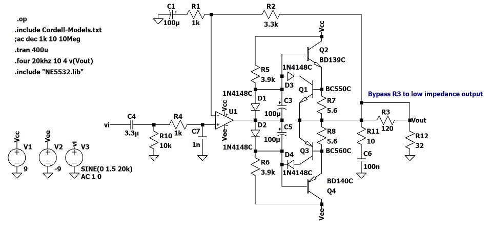
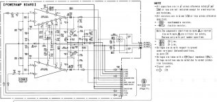
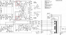
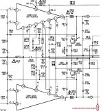
Yes the gain of the PA is about 37.6-37.7 dB, I've attached the power amp board schematic from Sony's repair manual.
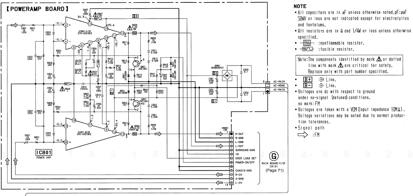
A few changes can be made to improve it, I need to look at it with more attention latter. 🙄
The preamp gain can be about 2-2.5x (6-8 dB), for typical sources, for now I've the gain you've suggested 2.5x in my schematic. And yes, I'm thinking about incorporating a phono preamp and a microphone preamp. The problem I'm seeing here is that the gain is very high for the PA, but very low for the HP amp, this will make the volume quite low on this last amp, for the phono and mic inputs, right? Maybe adjustable gain may be required for those two inputs? Even though HPs usually require a much lower voltage level to achieve the same SPL.
I've changed the schematic, to make the circuit non-inverting, with low impedance input drive and linear pots.
Are you suggesting that the NE5532 is not good enough? I have lots of them, and I was thinking about using it here, but I could also try one of the opamps you suggested, if they sound better. I'm not familiar with most of those opamps, the only one I know is the 4558, it incorporates a 70s-80s Grundig preamplifier, of a unit based on the STK461, I really like the sound that thing makes. Despite being far from a true HiFi amp. The headphone output sounds awesome.
I prefer to be able to operate both HP and PA simultaneously. Either way, it should offer the possibility to somehow mute the PA if needed, like for example, opening the output relay, activate the hybrid muting functionality, diverting the signal from the PA input to ground, or incorporating a relay or switch at the input of the PA. Which possibility do you think will be more appropriate?
Both HP and PA must have independent volume pots, and maybe a master pot is also needed. I haven't dropped the idea of using both the PA divider and a dedicated HP amp, so maybe actuating the output relay to mute the PA speaker output is the better option here?
I still haven't changed the preamp's PA output, because I'm still a bit confused 😕. About where to place the pots and the balance/tone controls.

I was looking for the reason why they used that configuration of the inputs, on that same Grundig amp of the 70s-80s, and you've answered my question, that's great.😀

Input bootstraping seems a really clever idea.😉
Is there any expression for the the impedance gain?
Unfortunately, the Sony PA board I have does not feature input bootstrapping. 🙁
Yes, I think you're right, the NJM4556A HP amp seems more straightforward and easier to implement, while also exhibiting superb performance. I'm no PCB wizzard, I've made a few PCBs myself, but I don't know exactelly how bad or how good they are compared to other boards. The best board I've made is an HP amp based on Rod Elliot's Project 113. I don't have laboratory equipment to test it for oscillations, but it does sounds good. 🙂
For a power consumption perspective, and also almost any other parameters, the O2 seems a winner, but making this PCB and seeing it working was really rewarding. 😉
For this project I will follow your suggestion and try the O2, do you know what is the cost of a O2 board in europe? I haven't decided if I'm going to make an O2 based board, which is more of a challenge or order an O2 board.
The main problem is the tone/balance controls which maybe should seat between the preamp and the O2 output buffers, perhaps a custom board will better fit the purpose.
Regards,
Danny
I was referring to levels ahead of the preamp.
But if you have that much power amp gain (any clue about the feedback network resistors?), I might consider reducing preamp gain. In practice with relatively high-level sources, a gain of 2.5X (8 dB) is often found to be easily sufficient, and in fact with CD player levels (0 dBFS = 2 Vrms) and typical HiFi headphones of 102-103 dB SPL / V (Sennheiser HD600/650, Beyer DT880 etc.), people are often running unity gain. I have often argued that the 1X/2.5X gain combo actually makes more sense for most people.
8 dB would give you very typical 85-100wpc integrated amplifier gain in total (45.7 dB). That's plenty enough even for a phono stage with some room to spare. Unity gain would still give you the 37.7 dB of the power amp, still more than enough for most non-phono sources.
Yes the gain of the PA is about 37.6-37.7 dB, I've attached the power amp board schematic from Sony's repair manual.
A few changes can be made to improve it, I need to look at it with more attention latter. 🙄
The preamp gain can be about 2-2.5x (6-8 dB), for typical sources, for now I've the gain you've suggested 2.5x in my schematic. And yes, I'm thinking about incorporating a phono preamp and a microphone preamp. The problem I'm seeing here is that the gain is very high for the PA, but very low for the HP amp, this will make the volume quite low on this last amp, for the phono and mic inputs, right? Maybe adjustable gain may be required for those two inputs? Even though HPs usually require a much lower voltage level to achieve the same SPL.
Hmm. I am actually fairly certain that the inverting Baxandall normally uses linear pots, that's part of its appeal. It should also be driven from a low-impedance source, so often a buffer is included. At line level, this could be something rather basic, MC33078 or LM833 or even NJM4558 or 4580 perhaps.
I've changed the schematic, to make the circuit non-inverting, with low impedance input drive and linear pots.
Are you suggesting that the NE5532 is not good enough? I have lots of them, and I was thinking about using it here, but I could also try one of the opamps you suggested, if they sound better. I'm not familiar with most of those opamps, the only one I know is the 4558, it incorporates a 70s-80s Grundig preamplifier, of a unit based on the STK461, I really like the sound that thing makes. Despite being far from a true HiFi amp. The headphone output sounds awesome.
That's why I suggested to tap off between one of the 4556 outputs and its 1 ohm combining resistors, where output impedance is super small and the effect of any loading would not show up in frequency response (only possibly in extra distortion).
I did make an oopsie last time and failed to consider the necessity of switching between speakers and headphones, sorry 'bout that. Maybe get a HP jack with an extra switching contact and use that to engage a 24 V relay between +/-12 V (dissipate any extra voltage via series R). 2x DPDT, maybe Au-plated contacts, nothing super huge required. Then the signal could be routed to the jack when plugged and to the speaker amp when unplugged.
I prefer to be able to operate both HP and PA simultaneously. Either way, it should offer the possibility to somehow mute the PA if needed, like for example, opening the output relay, activate the hybrid muting functionality, diverting the signal from the PA input to ground, or incorporating a relay or switch at the input of the PA. Which possibility do you think will be more appropriate?
Both HP and PA must have independent volume pots, and maybe a master pot is also needed. I haven't dropped the idea of using both the PA divider and a dedicated HP amp, so maybe actuating the output relay to mute the PA speaker output is the better option here?
I still haven't changed the preamp's PA output, because I'm still a bit confused 😕. About where to place the pots and the balance/tone controls.
That's a question possibly better answered by The Art of Electronics. The idea behind bootstrapping is that an input resistor will appear to be much larger than it actually is if the other end keeps actively tracking the input voltage. Feed in 90% of the input signal there, and the resistor will only carry 10% the current - it will appear to be 10 times as large. Likewise, the effect of input capacitance and input bias currents is similarly reduced, which can be important if the input transistors are run hot and have quite a bit of (nonlinear) input bias current that would cause substantial distortion when faced with high-impedance sources.
Now where do we get a suitable source for something like that? Well, try the inverting input for one. Here's a typical example, borrowed from a Grundig V5000:
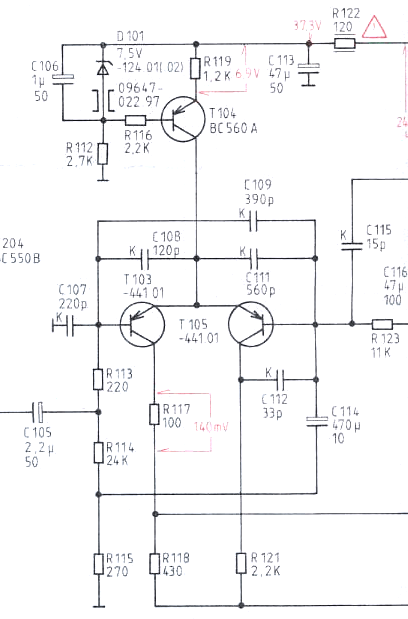
R123/(C114 + R115) is the classic feedback network. R and C have been switched around for convenience / saving parts, otherwise you'd need two caps here.
R114 is the input / bootstrap resistor.
This usually costs you some gain somewhere (the usual rule of thumb for bootstrapping is "higher input impedance, higher output impedance"), but it can't be that much here.
I was looking for the reason why they used that configuration of the inputs, on that same Grundig amp of the 70s-80s, and you've answered my question, that's great.😀
Input bootstraping seems a really clever idea.😉
Is there any expression for the the impedance gain?
Unfortunately, the Sony PA board I have does not feature input bootstrapping. 🙁
On the plus side, you get a proven known-good circuit and particularly board layout, and you can even buy a finished board or kit. If you're a layout wizard who regularly rolls their own boards this might not matter, but not a lot of people are. Remember, the layout is the circuit.
The pair of 4556As was chosen because it was easy, cheap, has moderate idle current consumption (important for battery operation) and generally gets the job done well enough. Can you do something better with another opamp and a discrete buffer, especially if power is no object? Of course. Will you have to do a bunch of simulating and troubleshooting to make it work 100%? You bet you will.
Yes, I think you're right, the NJM4556A HP amp seems more straightforward and easier to implement, while also exhibiting superb performance. I'm no PCB wizzard, I've made a few PCBs myself, but I don't know exactelly how bad or how good they are compared to other boards. The best board I've made is an HP amp based on Rod Elliot's Project 113. I don't have laboratory equipment to test it for oscillations, but it does sounds good. 🙂
For a power consumption perspective, and also almost any other parameters, the O2 seems a winner, but making this PCB and seeing it working was really rewarding. 😉
For this project I will follow your suggestion and try the O2, do you know what is the cost of a O2 board in europe? I haven't decided if I'm going to make an O2 based board, which is more of a challenge or order an O2 board.
The main problem is the tone/balance controls which maybe should seat between the preamp and the O2 output buffers, perhaps a custom board will better fit the purpose.
Regards,
Danny
Attachments
Last edited:
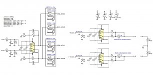
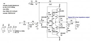
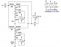
I've "extracted" the overload (short-circuit) detection circuit from the service manual, the schematic as I interpreted it, is attached. 😀
V1 is simulating the PA output, R1 is the S/C detection resistor, only one channel is represented.
The value that I used for capacitor C1, C284 (in service manual) is much lower 10 uF vs 220 uF. I've made this change because in simulation, it seems like it is reacting too slowly in some overload situations. I think it is better to detect this situations in less than 1s (the time available for loads shorted condition of the STK4231II), 0.1 seconds seems a reasonable value. Any idea why the manufacturer is using such an high capacitance value/time constant? Is there any difference if I use a BC550 or similar instead of a BN1F4M for Q2 (in schematic), Q282 (in service manual)? 😕
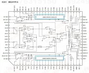
Just noticed, the original main board featured a 5 band equalizer, it is incorporated in a Mitsubishi IC, the M6247FP-A. 😛
Any idea how to reproduce the behaviour of this IC? If it is a good idea at all.🙄
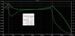
I've been trying (in LTSpice) a graphic equalizer design that is shown on some TI opamp datasheets, but I'm not sure how the values are determined, to achieve a certain Q, define the centre frequency and maximum/minimum gain. The circuit is showing peaking at 1 MHz when I adjust the pot to achieve maximum boost in the 34 Hz band (Rpot1f1=10k, Rpot2f1=1p), and the gain is set to about 16-17 dB, no idea about the Q. 🙁
Anyone knows the expressions of this circuit? Does this peaking means instabillity? Any graphic equalizer circuit suggestions? Or it will be better to stick with the simpler Baxandall tone controls and simply forget about that?😕
Regards,
Danny
V1 is simulating the PA output, R1 is the S/C detection resistor, only one channel is represented.
The value that I used for capacitor C1, C284 (in service manual) is much lower 10 uF vs 220 uF. I've made this change because in simulation, it seems like it is reacting too slowly in some overload situations. I think it is better to detect this situations in less than 1s (the time available for loads shorted condition of the STK4231II), 0.1 seconds seems a reasonable value. Any idea why the manufacturer is using such an high capacitance value/time constant? Is there any difference if I use a BC550 or similar instead of a BN1F4M for Q2 (in schematic), Q282 (in service manual)? 😕
Just noticed, the original main board featured a 5 band equalizer, it is incorporated in a Mitsubishi IC, the M6247FP-A. 😛
Any idea how to reproduce the behaviour of this IC? If it is a good idea at all.🙄
I've been trying (in LTSpice) a graphic equalizer design that is shown on some TI opamp datasheets, but I'm not sure how the values are determined, to achieve a certain Q, define the centre frequency and maximum/minimum gain. The circuit is showing peaking at 1 MHz when I adjust the pot to achieve maximum boost in the 34 Hz band (Rpot1f1=10k, Rpot2f1=1p), and the gain is set to about 16-17 dB, no idea about the Q. 🙁
Anyone knows the expressions of this circuit? Does this peaking means instabillity? Any graphic equalizer circuit suggestions? Or it will be better to stick with the simpler Baxandall tone controls and simply forget about that?😕
Regards,
Danny
Attachments
-
 Protection schematic - poweramp board.jpg204.1 KB · Views: 410
 -
 Protection schematic - main board.jpg105.6 KB · Views: 156
 -
 Overload Detection Circuit - v1.jpg144.5 KB · Views: 151
 -
 Graphic equalizer.jpg247.9 KB · Views: 128
 -
 Graphic Equalizer (full 34 Hz boost).jpg521.9 KB · Views: 135
 -
 Graphic Equalizer (Draft) - v1.jpg115.9 KB · Views: 163
 -
Graphic Equalizer - v1.asc3.4 KB · Views: 94
-
Output_protection_pa_board.asc2.9 KB · Views: 110
-
TL071.zip1 KB · Views: 107
Last edited:
Power Pack STK4231II
I am fading with a Teac A-R500 amplifier that uses the Power Pack STK4231II as the ending, from a first check it seems that there is a channel that is wrong. Question is never possible that using that handyman ending in which two channels are incorporated there is a single channel that does not work, in my opinion it should not work both someone has experience in this regard thanks Giampietro Italy
I am fading with a Teac A-R500 amplifier that uses the Power Pack STK4231II as the ending, from a first check it seems that there is a channel that is wrong. Question is never possible that using that handyman ending in which two channels are incorporated there is a single channel that does not work, in my opinion it should not work both someone has experience in this regard thanks Giampietro Italy
- Home
- Amplifiers
- Chip Amps
- STK4231II based amplifier