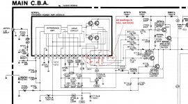
RCA MPA-120. I have two of these amps, so 3 good channels to compare voltages. The channel in question has VAC readings as shown in the pic on what appear to be the STK output legs. The readings are AC Volts, not mili-Volts. The three good channels do not look like this.
Could something other than a bad STK be causing this?
In working with these amps I have found lots of bad solder joints as well as several capacitors that are completely shot, i.e. reading 0uF.
I don't have o-scope-ability, but plugging in a speaker the voltage sounds like 60Hz or 120Hz. Not very loud but its there.
Bad STK...or possibly something else?
Attachments
Last edited:
It’s probably oscillating at ultrasonic frequency. This often comes with a power hum, as the amp is actually working hard - you just can’t hear it. See if the resistor in the zobel network (not on the partial schematic, would be off the page to the right) is getting hot or is already burnt out.
You say you found some bad electrolytics. That could very well be the case - if the bypass caps or feedback DC block are bad you can get oscillation. Don’t let this go on too long because it could kill the module.
You say you found some bad electrolytics. That could very well be the case - if the bypass caps or feedback DC block are bad you can get oscillation. Don’t let this go on too long because it could kill the module.
Thank you wg_ski
The NFB cap is one of the ones that was completely shot. Same thing on all four channels (both amps), that cap was reading 0.0uF. But that has been replaced with a new (and tested) Muse ES bipolar.
Is the zobel network a resistor in parallel with a coil?
Which are the bypass caps? Are they showing in this schematic snippet?
I removed R721L which i believe to be the zobel resistor. It reads approximately .1 ohm and it should be 10 ohm according to the schematic.
I will post that part of the schema shortly.
But looks like a good call wg_ski !
I will post that part of the schema shortly.
But looks like a good call wg_ski !
So assuming this is the cause of the issue, would any damage have been done to the STK itself? Weakened it in some way as to make it vulnerable, or shorten its life span? I need to make a decision whether or not to do a full recap on this unit.
I have no idea the history of this amp. It came to me with this problem and another that I already fixed. I have not hooked it up to speakers other than that one very brief listening test. But...I have let it sit and idle maybe for a couple hour while it was, apparently, in oscillation...
I have no idea the history of this amp. It came to me with this problem and another that I already fixed. I have not hooked it up to speakers other than that one very brief listening test. But...I have let it sit and idle maybe for a couple hour while it was, apparently, in oscillation...
R721L, which I removed from the amp and marked in this pic, reads approx .1 ohm (my DMM is not very accurate). It should be 10ohm according to the schematic.
Would this be the sole cause of the issues I am seeing?
And does anyone know what the symbol means, resistor enclosed in a rectangular box?
Would this be the sole cause of the issues I am seeing?
And does anyone know what the symbol means, resistor enclosed in a rectangular box?
Attachments
If that resistor is reading .1 ohm it could be a problem, might not. Might even be the source of the oscillation. If it’s off I’d replace it. The zobel resistor is R722, in series with a cap to ground. It acts as a high frequency load for the amp and will try to absorb all the power if driven at very high frequency (possibly burning up).
The box probably indicates the resistor is “fusible”, meaning it’s intended to fail open circuit if overloaded. Going low in value would be weird.
You only really hurt the module if it runs HOT while oscillating. Depending on how high in frequency and the actual amplitude. You can’t count on that 0.7 volt AC reading, because he DMM probably reads low at that kind of frequency.
Feedback caps being bad can result in lower than normal closed loop gain. There is usually a minimum stable gain for most feedback amplifiers. If it’s too low, it oscillates. This type of over all loop oscillation is usually non-destructive but there are exceptions. Local oscillations in the output stage can be destructive, but there are exceptions.
D'oh! 😱
I made a mistake. I removed R712L instead of R721L.
R712L is .22R so the reading I have for it is well within the margin of error of my cheap DMM.
-------------------------------
I will put that resistor back in. Then I will check the zobel resistor R722L
Just to be clear, the NFB cap was replaced prior to me posting here. The only amp behavior I have observed was the left meter showing output even with no input signal. The meter behaved the same before and after installing the new NFB cap.
Thanks again wg_ski
R712L back in place
R721L lifted one leg and it reads 10.0 ohms perfect
Neither of the two above were mentioned as suspects. But at least it is good to know that if R721L is a fusible, that its resistance is still in spec
R722L reads 4.7 ohms as per the schematic. It looks clean, not like it has ever over heated.
After idling for 1/2 hour R722L is cool to the touch.
With the amp on, R722L has 0 VDC across it, and .02 VAC across it (R722R in the good channel has .018 VAC across it).
@ wg_ski I think I found the problem! Thanks again 
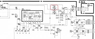
R707L connected to pin 4 of the STK. Supposed to be 10K ohms. It reads inconsistently on my LCR meter, 60K one time, 200K another.
Replaced it with a new resistor and the bad channel is now behaving just like the good channel.
Looks like there is some kind of black corrosion on one end of this resistor that is not present on most of the others. Unfortunately, there are a few others that do look like this one. Maybe I need to replace them too?
Attachments
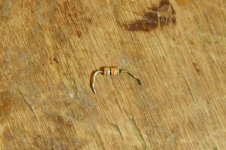
Corrosion. Replace all you can find.
Once you are done repairing the amp. wash the boards with dish wash soap, rinse, dry as if it was a utensil.
Leave it overnight in a warm room, or for some time in sun light.
Then coat the whole thing with PCB protector spray, or insulating varnish on solder and component sides.
Dry before powering up.
That will cut off air from the components.
No air, no oxygen means no corrosion.
And do remove flux traces and residues before doing this.
Last edited:
- Home
- Amplifiers
- Solid State
- STK amp with .67 VAC on output