Duelbox,
It sounds like that guys problem was caused by rebar in his concrete appartment floor. Definitley not an issue here. The speaker cable position does make a big difference, but holding it completely off the floor can be much better, or much worse, depending on the positonl.
Eva,
I don't have a 'scope.
Per-Anders,
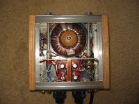
I just quickly shorted the input to ground at the board and the noise is identical except ever so slightly louder. It would be difficult to power up one channel at a time. If a short cable would make the results much different I'll give that a shot. My normal cables are only 2 meters long, very low inductance and fairly low capacitance. The IC is the insulated version with heat sink compound between it and the heatsink. I tried to attach a pic of the inside.
Neutron7,
I don't think a filter at the input would help, as I'm fairly convinced it's noise from the speaker cables being amplified through the feedback circuit. When I get some ferrites I'll be more sure.
thanks all,
Paul
It sounds like that guys problem was caused by rebar in his concrete appartment floor. Definitley not an issue here. The speaker cable position does make a big difference, but holding it completely off the floor can be much better, or much worse, depending on the positonl.
Eva,
I don't have a 'scope.
Per-Anders,
I just quickly shorted the input to ground at the board and the noise is identical except ever so slightly louder. It would be difficult to power up one channel at a time. If a short cable would make the results much different I'll give that a shot. My normal cables are only 2 meters long, very low inductance and fairly low capacitance. The IC is the insulated version with heat sink compound between it and the heatsink. I tried to attach a pic of the inside.
Neutron7,
I don't think a filter at the input would help, as I'm fairly convinced it's noise from the speaker cables being amplified through the feedback circuit. When I get some ferrites I'll be more sure.
thanks all,
Paul
Attachments
I got impatient and bought some big rectangle shaped chokes at radioshack. The big skinny things only helped a little when snaped over my cross connected coax speaker cables. I used a short lenght of zip cord and wound it through 8 times, as the instructions suggest to acheive a 23db attenuation at 100Mhz. That practically eliminated the problem. With it in place, I have to put my hear right up to the cone to hear any noise, and then it is just a soft hiss rather than muffled voices.
I am curious about a bandwidth limiting network on the speaker cable, similar to what Transparent does. Any suggestions?
Paul
I am curious about a bandwidth limiting network on the speaker cable, similar to what Transparent does. Any suggestions?
Paul
pjanda1 said:I've got a BrianGT NI3875 that is very minimalist and I have been having some noise issues.
(FM, I can hear the announcers with my ear up to the 94db sensitive speaker)
Building minimalistic means removing components
that are otherwise good sense to use in amplifiers.
An experienced designer would never build an amplifier without some way limiting what enters input.
A) Proper sheilding of cable and PCB rails/wires, that carry input signal
B) Low pass filter by grounding signals above 300-500 kHz
Such a filter is easy and simple.
A little cap from input to ground.
You should study this topic we had a few weeks ago:
Reduce input noise
")
If this were input noise, why would using chokes on the speaker cables make it go away? Wouldn't shorting the inputs at the amplifier board (a couple of mm from the chip) reduce the noise? Why would just moving the speaker cables make a huge difference? The noise is similar whether I switch to a shorted input or an unshielded interconnect (my normal cables are shielded.) I'll be the first to admit I don't know much, so please explain how these are symptoms of noise at the input.
I don't mean to sound confrontational, as I'm looking for help from those more experianced than I. However, I believe I've identified the problem (actually someone else did, I just confirmed it.) I'm now looking for all possible solutions.
Paul
I don't mean to sound confrontational, as I'm looking for help from those more experianced than I. However, I believe I've identified the problem (actually someone else did, I just confirmed it.) I'm now looking for all possible solutions.
Paul
Without these very weak signals being going into input
and amplified, there can not be anything you can hear.
Speaker cable can help act as antenna
and give more or less signal to your input, via for example ground connection.
But the issue is to protect from letting these radio/noise signals enter into amplifier
and so get amplified.
Only your music, audio frequencies, should be amplified.
The rest should be avoided, with a filter at the input that blocks high freq signals/noise.
Can be, as metioned a small cap between + and - input.
Or as most often, a small cap from input to ground.
Besides cable shielding, also how well the chassis shields can effect.
An all wooden case or an open case
does not keep noise way,
as good as an all aluminium and sealed amplifier case.
Keep things neet and tidy is a virtue. A ratsnest can be good or a disaster, never can tell.pjanda1 said:
Per-Anders,
I just quickly shorted the input to ground at the board and the noise is identical except ever so slightly louder. It would be difficult to power up one channel at a time.
Looking from the picture I'm sure you can improve the wiring, keep input apart from the output, use shielded wires if necessary.
Having output wires very close the input is not a very good idea.
As lineup says:
Building minimalistic means removing components
that are otherwise good sense to use in amplifiers.
I have used some basic parts (according to me) and that is a zobel network and an output filter. It's better to have room for basic filters to cover 99% of all normal applications but in this case Brian and Peter have thought that less is more. My idea is to add just in case parts because it's easier to exclude them than patching them in afterwards.
... so if you can't make a shorten single pcb be quite you have some basic trouble in the mounting.
You don't have a possibility to borrow an oscillscope? Very much easier to troubleshoot.
You may call a design "minimalistic" but there are things that should never be left out, like a RC low-pass input filter. Several years ago, the first chip amp that I ever built *exploded* when I touched the input signal wire with my fingers, because I was too lazy to solder the input filter capacitor.
I'm still interested in an explanation of how chokes on the speaker cables are making input noise disappear.
I don't think "good sense" and "best sound" often go hand in hand. For example, I tried using a zobel and it did nothing to help while making everything sound constricted and distant. If I had high capacitance cables or a difficult to drive speaker, then it would be good sense to include it. As I don't, I don't see why I should have useless parts.
I don't doubt that an input filter is safer and can help in many situations. It is fairly obvious to me that 95% of my noise is coming from the speaker cables. When that noise is removed by the choke, the amp is quieter than many high end rigs I've heard. Unless I'm misunderstanding what the chokes are doing, anything at the input would solve 3% of my problem at best. However, if I get some extra time today, I'll solder up and input filter so we can all stop discussing it.
Per-Anders,
The wiring is a bit messy, but I'm having a hard time doing better in the small space I gave myself. I have been thinking that I should rework it. I suppose I could take it to a shop and have them use an oscilliscope. What could I have done wrong in the PCB/chip mounting? What output filter do you like to use?
I would suggest to find two old ferrite rods ( about 20 cm's long) from an old am-reciever, and wind your speaker cables around it. If you have enough length, then 30-40 turns might do the trick.
Sound like you are picking up some HF, that gets detected somewhere in the output stage.
This trick have worked for me a couple of times, i had that problem when i was into hamradio, where the strong signals went into my lf-system.
Good luck
Sound like you are picking up some HF, that gets detected somewhere in the output stage.
This trick have worked for me a couple of times, i had that problem when i was into hamradio, where the strong signals went into my lf-system.
Good luck
pjanda1:
You are messing things up a lot, probably due to a lack of understanding of electronics. That noise was *never* ever coming from the speaker wire, you can check it by yourself: Try to disconnect the wires from the amplifier binding posts and short them instead. Your noise will disapear. If you power off the amplifier, the noise will also disappear, and the same will hapen if you short the binding posts with the amplifier turned on, altough this may cause te protecion of the ICs to kick in. Finally, you may try to activate the MUTE function of the ICs and the noise will also disapear.
The noise is being picked up at the amplifier ICs, that are oscillating and acting as AM/FM receivers due to bad layout or bad design. It has been said several times. I've experimented that kind of problems in all its flavours, it happened in all my very first designs with audio ICs, as I was using point to point with long wires and no RF filtering nor decoupling.
If you had an oscilloscope, you would be able to see the RF oscillation components on the supply rails and the outputs of the ICs. In fact, most simple radio receivers are just based on an oscillator
I put an lpf right at the inputs to the board. To my surprise it had exactly the same effect as using the choke on a speaker cable: most but not all of the noise is gone.
I still want to believe that the noise is entering via the speaker cables and being amplified in the feedback loop. Since this filter connects at essentially the same juncture as the feedback resistor, isn't it possible that it is filtering that noise?
For the last time, if the noise is not coming from the speaker cables, why does the ferrite eliminate it? Why does moving the speaker cable make a huge difference? I do not have a broad understanding of electronics, but anyone is welcome to come over the my house and listen to the choke take care of the noise. Please answer the question. I know I am in no place to argue, but I have yet to hear an explanation of how the noise can be eliminated by chokes on the speaker cables if it does not come from the speaker cables!
Finally, this (noise from the speaker cable to the feedback loop) was not my theory. I was discussing this problem on a different forum, and this theory came from a respected DIY'er, amplifier designer, and E.E.
Thanks, es44, I'll try the rods too. I think they'll be easy to find inexpensively.
Paul
The RF signal enters in small amounts through the signal wires (it's always present so the circuit must cope with it). This small amount of RF is amplified by the oscillating IC and then re-radiated by the speaker wire, the mains transformer and wiring and everything, and picked up back by the signal wires.
The two keys for success are to keep the input of the IC as free from RF as possible, and to prevent the IC from oscillating.
Could you post detailed pictures of the PCB layout?
The two keys for success are to keep the input of the IC as free from RF as possible, and to prevent the IC from oscillating.
Could you post detailed pictures of the PCB layout?
Thanks alot, that's the explanation I was looking for. I built the LPF quickly out of the cheapest components radioshack had. I used a 1K resistor and 330pf cap. I'll likely order some parts that are better suited, so I wanted to make sure the values are ideal.
How about this:
http://www.chipamp.com/lm3875rev3.pdf
I'm having a hard time getting pics of my setup that show anything. Let me know if you want a close up of something in particular and I'll give it a shot.
How about this:
http://www.chipamp.com/lm3875rev3.pdf
I'm having a hard time getting pics of my setup that show anything. Let me know if you want a close up of something in particular and I'll give it a shot.
The short feedback path (soldering resistor between pins like is common) basicaly reduces common induction with the load.... didn't we tell you to put a small ceramic over the inputs as per the datasheet when you mentioned the RF problem innitialy, or am I thinking of someone else?
also
"If highly capacitive
loads are expected due to long speaker cables, a
method commonly employed to protect amplifiers from low
impedances at high frequencies is to couple to the load
through a 10Ù resistor in parallel with a 0.7 ìH inductor. The
inductor-resistor combination as shown in the Typical Application
Circuit isolates the feedback amplifier from the
load by providing high output impedance at high frequencies
thus allowing the 10Ù resistor to decouple the capacitive
load and reduce the Q of the series resonant circuit. The LR
combination also provides low output impedance at low
frequencies thus shorting out the 10Ù resistor and allowing
the amplifier to drive the series RC load (large capacitive
load due to long speaker cables) directly."
Hard to say what you have missed when whe don't can see it.pjanda1 said:What could I have done wrong in the PCB/chip mounting? What output filter do you like to use?
The filters I have used can be seen if you download the schematics of my two Gainclones (see my homepage).
I really recommend that you take a close look at the datasheet and the application note AN-1192. I know many of you can't understand all of it but surely some. I think it's pretty clear written how you basically should connect the IC.
I figured I'd update the thread to reflect my success.
I first tried to rewire it and change the grounding scheme. I eliminated a couple of extra inputs, cleaned up the routing, and used twisted pairs (cat5) for all signal. I tied PG+ and - on the amp boards and the PS. I used one wire from the center of the ground connection on each board too the center of the PS. I ran one wire from there to the chassis ground. If I interpreted correctly, some folks thought this would reduce crosstalk compared to Carlos's scheme. However, I had far more hum than the stock setup.
I lived with that for awhile, then ordered some 300pf film caps. I installed them on the board from input to ground. I also switched to Carlos's grounding scheme, as detailed here:
http://www.diyaudio.com/forums/showthread.php?s=&threadid=57526&highlight=
It is now awfully quiet. I can still hear a faint hiss with my ear up to the speaker, but that is fine. There is not a hint of 60hz hum. It sounds a bit different. I can't put my finger on how. It seems clearer, but also a bit constipated. Perhaps it's just cold.
I appreciate everyone's patience. Hopefully this post will have some educational value for other stubborn folks. I'd also recommend that anyone with very sensitive speakers consider applying Carlos's grounding scheme in the initial build.
- Status
- This old topic is closed. If you want to reopen this topic, contact a moderator using the "Report Post" button.
- Home
- Amplifiers
- Chip Amps
- Still have noise.