Hi there,
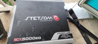
Can anyone assist me with a Stetsom Ex5000Eq amplifier that give out DC on the speaker terminals? The positive terminal has over 40 VDC and the negative has 3.8 VDC. I checked the voltage at the power input stage and there is a voltage drop of over 4 voltes. All of the Power FETs and output FETs give an ok reading during testing.
Any help will be greatly appreciated.
 Moved to Car Audio.
What do you mean by:
I checked the voltage at the power input stage and there is a voltage drop of over 4 voltes.
Most of the Brazilian amps have an H-bridge output and a single-ended supply so you'll see 1/2 of rail voltage on the speaker terminals. I'm not sure if that's true with this amp but should be easy to confirm if the source leg of half of the output FETs read 0 ohms to the primary ground.
Thanks for your reply.What do you mean by:
I checked the voltage at the power input stage and there is a voltage drop of over 4 voltes.
Most of the Brazilian amps have an H-bridge output and a single-ended supply so you'll see 1/2 of rail voltage on the speaker terminals. I'm not sure if that's true with this amp but should be easy to confirm if the source leg of half of the output FETs read 0 ohms to the primary ground.
The rail voltage is 77 volts on one side and Yes, I'm getting approximately 39 volts half the on the positive speaker terminal which gives out a humming sound with the speaker pulled in. The low side has a rail of approximately 8 volts and just over 3 volts on the negative speaker terminal.
For the above question, I meant the amplifier's B+ terminal. I supplied 12v and when I test the voltage across the B+ and B- I'm getting below 8 volts
Does it pull the 12v down with no speaker connected?
How much current is it drawing (no speaker load)?
How much current is it drawing (no speaker load)?
It draws 5 amps of current and yes it was pulling the voltage down without any load.Does it pull the 12v down with no speaker connected?
How much current is it drawing (no speaker load)?
Yes I do have a scope and no I did remove the board from the sink but I will. I thought there wasn't a reason to remove it since there isn't any components under it. and there is enough space to work inside the amp. I have checked for grounding on the FETS and found one power mosfet was drain was making contact with ground which was caused the amp to go into protect. the amp is no longer in protect but there is no audio but noise on the positive speaker terminal. I them placed one side of speaker wire on the neg terminal and the other heat sink of the amp and is getting output signal which is low (in reference to the low 3.8v on the the terminal) I'm wondering if the ground is broken somewhere on the board
I should inform you that I do not clearly understand the way that the Brazilian amps function.
I should inform you that I do not clearly understand the way that the Brazilian amps function.
You don't need to take the board out of the heatsink yet. I was just asking.
Do you understand the basic operation of floating high-side driver ICs?
Do you see any rail-rail oscillation on either group of output transistors?
What are the output drivers being used in this amp?
The Brazilian amps are different but the output stage is typically built around a generic driver IC, so that helps.
I just return from work.
Yes, I know about the Driver ICs BUT the specific word "Floating high-side" I never heard before.
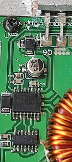
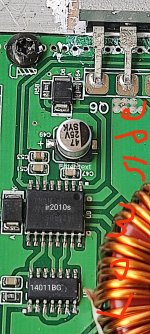
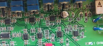
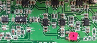
the output driver is IR2010s U9 and U10 but there is an IC 14011BG U7 and U8 in the same circuit and connected to the IR2010s on pin 3 I think. I will give better info and take photos of same and post them in the morning.
Yes, I know about the Driver ICs BUT the specific word "Floating high-side" I never heard before.
the output driver is IR2010s U9 and U10 but there is an IC 14011BG U7 and U8 in the same circuit and connected to the IR2010s on pin 3 I think. I will give better info and take photos of same and post them in the morning.
The low-side driver section is referenced to the negative rail (ground, here). The high-side driver section floats with the source of the high-side FET and has a floating supply.
Do you know how to use your scope in differential mode?
Do you know how to use your scope in differential mode?

Good day Mr. Perry.
These are the photos as promised.
(Deferential mood)I not sure if you are referring to switching channel 2 to add and pressing the invert switch down to avoid contact with ground when testing using both probe
These are the photos as promised.
(Deferential mood)I not sure if you are referring to switching channel 2 to add and pressing the invert switch down to avoid contact with ground when testing using both probe
Attachments
-
 IMG_20220731_164053.jpg372.9 KB · Views: 77
 -
 IMG_20220731_164720.jpg381 KB · Views: 69
 -
 IMG_20220731_164927.jpg366.4 KB · Views: 67
 -
 IMG_20220731_165353.jpg419.7 KB · Views: 75
 -
 IMG_20220731_165512.jpg463.6 KB · Views: 65
 -
 IMG_20220731_165536.jpg520 KB · Views: 64
 -
 IMG_20220731_165927.jpg520.2 KB · Views: 69
 -
 IMG_20220731_170201.jpg226.7 KB · Views: 72
 -
 IMG_20220731_164026.jpg364.4 KB · Views: 66
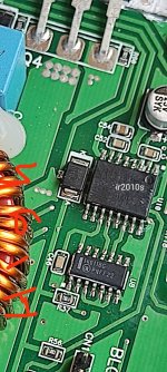
Do you see any rail-rail oscillation on either group of output transistors?
For what you marked as low-side, do all of the source legs of the output FETs read 0 ohms to ground?
For those not familiar with differential mode:
A differential input uses two inputs to produce a single waveform. The simplest way to get a differential input is to use a differential probe. A differential probe has two signal leads and a mixer amplifier built into it. It feeds the scope a normal signal (a composite of the two signals input into the differential probe). The problem with differential probes is that they're expensive.
The alternative is to use two scope probes and and both inputs of your oscilloscope. This is how you have to set up your scope:
Two probes
Both scope inputs used
Input set to add
Both channels set to DC coupling
Both channels set to 'cal'.
Both vertical amps set to the same voltage
Ch2 input set to invert
Bandwidth limited (works best for most measurements in car amps)
Trace aligned to the reference line on the scope's display
Ground leads for both probes connected together (not always necessary)
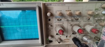
After setting up the scope, you need to confirm that it's working as it should. With the vertical amp set to 5v/div, touching the probe that's connected to Ch1 to the positive terminal of your 12v power supply should make the trace deflect about 2.5 divisions up from the reference (like it always does, seen below). Doing the same with the probe connected to Ch2 should make the trace deflect down about 2.5 divisions. Touching both probes to the positive terminal of the 12v power supply should cause no deflection. If it does, something isn't right.
I know that this may not be as simple as the isolated scope but if you take the time to learn it one time (even if it takes an hour or more of your time), you have that knowledge and this tool to use for the rest of the time you need to use a scope. Using the analog scope will give you much larger and cleaner waveforms.
For what you marked as low-side, do all of the source legs of the output FETs read 0 ohms to ground?
For those not familiar with differential mode:
A differential input uses two inputs to produce a single waveform. The simplest way to get a differential input is to use a differential probe. A differential probe has two signal leads and a mixer amplifier built into it. It feeds the scope a normal signal (a composite of the two signals input into the differential probe). The problem with differential probes is that they're expensive.
The alternative is to use two scope probes and and both inputs of your oscilloscope. This is how you have to set up your scope:
Two probes
Both scope inputs used
Input set to add
Both channels set to DC coupling
Both channels set to 'cal'.
Both vertical amps set to the same voltage
Ch2 input set to invert
Bandwidth limited (works best for most measurements in car amps)
Trace aligned to the reference line on the scope's display
Ground leads for both probes connected together (not always necessary)
After setting up the scope, you need to confirm that it's working as it should. With the vertical amp set to 5v/div, touching the probe that's connected to Ch1 to the positive terminal of your 12v power supply should make the trace deflect about 2.5 divisions up from the reference (like it always does, seen below). Doing the same with the probe connected to Ch2 should make the trace deflect down about 2.5 divisions. Touching both probes to the positive terminal of the 12v power supply should cause no deflection. If it does, something isn't right.
I know that this may not be as simple as the isolated scope but if you take the time to learn it one time (even if it takes an hour or more of your time), you have that knowledge and this tool to use for the rest of the time you need to use a scope. Using the analog scope will give you much larger and cleaner waveforms.
I setup the scope in differential mood but when I power up the amp this morning it had a huge voltage drop of half the output voltage of the power supply and it power cycling where by it appears that it is shutting down and restarting within a spit second. All voltage and wave form will go down to 0 the shoots back up within a second.Do you see any rail-rail oscillation on either group of output transistors?
For what you marked as low-side, do all of the source legs of the output FETs read 0 ohms to ground?
For those not familiar with differential mode:
A differential input uses two inputs to produce a single waveform. The simplest way to get a differential input is to use a differential probe. A differential probe has two signal leads and a mixer amplifier built into it. It feeds the scope a normal signal (a composite of the two signals input into the differential probe). The problem with differential probes is that they're expensive.
The alternative is to use two scope probes and and both inputs of your oscilloscope. This is how you have to set up your scope:
Two probes
Both scope inputs used
Input set to add
Both channels set to DC coupling
Both channels set to 'cal'.
Both vertical amps set to the same voltage
Ch2 input set to invert
Bandwidth limited (works best for most measurements in car amps)
Trace aligned to the reference line on the scope's display
Ground leads for both probes connected together (not always necessary)
After setting up the scope, you need to confirm that it's working as it should. With the vertical amp set to 5v/div, touching the probe that's connected to Ch1 to the positive terminal of your 12v power supply should make the trace deflect about 2.5 divisions up from the reference (like it always does, seen below). Doing the same with the probe connected to Ch2 should make the trace deflect down about 2.5 divisions. Touching both probes to the positive terminal of the 12v power supply should cause no deflection. If it does, something isn't right.
I know that this may not be as simple as the isolated scope but if you take the time to learn it one time (even if it takes an hour or more of your time), you have that knowledge and this tool to use for the rest of the time you need to use a scope. Using the analog scope will give you much larger and cleaner waveforms.
This amp setup is so different from the generic classes of amps.
Should I remove the input and output Fets and the regulators before doing anything else? I really don't want to make the amp worst than it is.I setup the scope in differential mood but when I power up the amp this morning it had a huge voltage drop of half the output voltage of the power supply and it power cycling where by it appears that it is shutting down and restarting within a spit second. All voltage and wave form will go down to 0 the shoots back up within a second.
This amp setup is so different from the generic classes of amps.
Lift the SD terminals for the IR2110 driver ICs and connect those SD terminals to the VDD supply terminals with a small jumper wire. This will disable the drivers.
Does the amp remain on with the driver ICs disabled?
Does the amp remain on with the driver ICs disabled?
I checked the output FETS andI observed Q9 alone source leg reads 0 to ground and Q3 gives a high reading of .806I setup the scope in differential mood but when I power up the amp this morning it had a huge voltage drop of half the output voltage of the power supply and it power cycling where by it appears that it is shutting down and restarting within a spit second. All voltage and wave form will go down to 0 the shoots back up within a second.
This amp setup is so different from the generic classes of amps.
Did you see post #17?
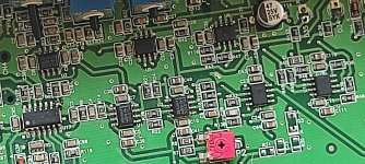
In an all N-channel, H-bridge configuration...
There has to be at least two output FETs with their source legs connected directly to ground (which is the negative rail, for this amp).
There also has to be at least two output FETs with their drains connected to the positive rail voltage.
In an all N-channel, H-bridge configuration...
There has to be at least two output FETs with their source legs connected directly to ground (which is the negative rail, for this amp).
There also has to be at least two output FETs with their drains connected to the positive rail voltage.
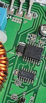
Yes I did remove the shut down pin but didn't connect the vdd. I how ever removed the board from the heatsink and got one bad power supply FET. I removed it and the amp power up perfectly but the half rail on the speaker terminal is not present. There is now a very low voltage on the terminal and the speaker now play very low in reference to the low voltage.Did you see post #17?
In an all N-channel, H-bridge configuration...
There has to be at least two output FETs with their source legs connected directly to ground (which is the negative rail, for this amp).
There also has to be at least two output FETs with their drains connected to the positive rail voltage.
In reference to what you said above yes, there are two output FETs source - one on each side of the amp - directly connected to ground.and two to the positive rail.
Also square waves are on all the FETS and all components I checked reads ok.
Should I resolder the shut down pin or continue to disable it?
- Home
- General Interest
- Car Audio
- Stetsom Ex5000Eq DC on speaker terminal