Is there anybody who could assist with this low rail voltage issue? The problem is that the rail voltage is +88v when it should be at least +125-140...
Maybe this question can be answered. What is the potential danger in using this amplifier in this condition? It plays clear audio on the test bench. The PS FETs gate voltages are the same as the working amp and the outputs have the correct voltages on each leg considering the lower than normal rail voltage. Is the worst that would happen is that rms output would be reduced, or is it possible that something could blow up? I guess that would be one way to find the faulty item...
Hoping that as I provide more information, someone can chime in with some suggestions...
The amp works fine. I tested it in a vehicle and it put out clean bass all the way up to the point where the clip light started to blink lightly, and I didn't go any higher than that. There doesn't seem to be any defective components in the amp but it definitely doesn't have the level of power it had prior to this repair. With the vehicle running and B+ terminal voltage at 14.1v, the rail voltage was +104v. At the most extreme bass notes, the rail voltage dropped all the way down to +79v, but no lower than that. I remember when I first got this amp the rail voltage was somewhere around +130-140 something running on my power supply which puts out 13.8v. The 2ohm Stetsoms I have idle at around +135v running on the same power supply.
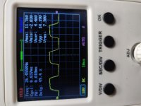
I attached pics of the drive signal of both amps. powered both amps up side by side and checked the drive signal at the PS FET gates of both amps and they are almost identical, so I assume the drive signal can be ruled out. I also resoldered the connections of the transformer windings where they enter the board, in case that had anything to do with it. All the heatsink mounted components read identical in both amps.
I do not understand amplifier design enough to know positively what to change/adjust but I think that there must be some capacitor/resistor/diode that is out of tolerance and not providing the correct value to a circuit or IC however I haven't come across that component yet. I also don't know what is responsible for control of the rail voltage. I am just taking shots in the dark here...
The amp works fine. I tested it in a vehicle and it put out clean bass all the way up to the point where the clip light started to blink lightly, and I didn't go any higher than that. There doesn't seem to be any defective components in the amp but it definitely doesn't have the level of power it had prior to this repair. With the vehicle running and B+ terminal voltage at 14.1v, the rail voltage was +104v. At the most extreme bass notes, the rail voltage dropped all the way down to +79v, but no lower than that. I remember when I first got this amp the rail voltage was somewhere around +130-140 something running on my power supply which puts out 13.8v. The 2ohm Stetsoms I have idle at around +135v running on the same power supply.
I attached pics of the drive signal of both amps. powered both amps up side by side and checked the drive signal at the PS FET gates of both amps and they are almost identical, so I assume the drive signal can be ruled out. I also resoldered the connections of the transformer windings where they enter the board, in case that had anything to do with it. All the heatsink mounted components read identical in both amps.
I do not understand amplifier design enough to know positively what to change/adjust but I think that there must be some capacitor/resistor/diode that is out of tolerance and not providing the correct value to a circuit or IC however I haven't come across that component yet. I also don't know what is responsible for control of the rail voltage. I am just taking shots in the dark here...
Attachments

Last edited:
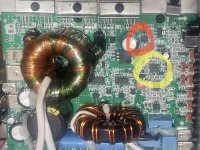
The red circled IC is the driver IC for the power supply mosfets. The regulation is controlled by the yellow circled IC.
Judging by the drive signal photos you posted, your drive looks normal so I wouldn’t suspect the driver IC.
It’s possible that you could have a defective transistor in the power supply. Could be a blown trace, a bad solder joint, defective passive component in the power supply located close to the transistors or a defective transistor.
Other than that, check the output inductor for a broken winding where it connects to the board. Those inductors that are mounted standing up like that have a tendency to break their connection to the board where they connect to the board. I have seen them completely snapped off and I’ve seen them almost broken, but still barely connected. None the less damaged.
It’s possible you could have a shorted cap, somewhat rare in these amps or it could be a defective output transistors pulling the rail voltage down. It’s gonna come back down to looking for components heating up or not operating altogether. Checking the voltages at each component for anomalies. You may have to pull the power supply mosfets from the board and check them out of circuit. The same may be necessary for the output mosfets as well.
Check the voltage at the speaker terminals as referenced to ground. You should have equal voltage on each speaker terminal and it should be equal to half of the rail voltage. So that’s the black probe of you DMM on the ground terminal and the red probe on each of the speaker terminals one at a time. They should be equal (within a volt or two) and half the rail voltage.
Attachments
Thanks so much for the reply. I will try all of the above except for the IC that controls regulation. The legs on that IC are way too small for me to do anything to it except change it. I will report back with my findings regarding these checks...
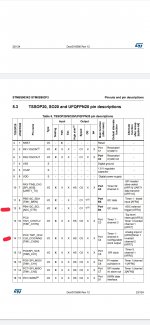
Asking for help again regarding this amplifier. The amplifier has been in use for the past three months without issues or failure. I would still like to get the rail voltage back up to what it is supposed to be. I have 2 other properly working EX3000s but 2 ohm models so I am unsure what all is different between the two models. I recently had to repair a Timpano 3000 which is the same exact amp so I ended up having to take voltage readings of the regulation IC, STM8S903. All four amps had most of the same voltages on the legs of this IC. This amp differed from those amps on 2 legs of this IC which deal with clock and timer functions. I done fully understand this IC and how it functions so I thought I would ask while I simultaneously study it. In the amp with +140v of rail, there is +0.7/+0.8 on legs 12 and 14 of this IC. In this amp with +100v of rail, there is +1.0v on both legs 12 and 14 of this IC. All other legs of this IC has identical readings in all the amps. My assumption is that if those legs were reading +0.7/+0.8v, the rail would go back up to +140v. Can anyone share some insight? The posted pics are if the readings in this amp, and one with +140v of rail. As mentioned, the amp is fully functional, just doesn't hit as hard as it did prior to this repair. Thanks
Attachments


Last edited:
I cannot find anywhere that pins 12 and 14 connect to, so the only other thing I can think of is that the IC is compromised internally or that some other pin's input is the cause for the low Rail voltage. I really don't understand the whole regulation process and these pins may be effect, and not cause but if anyone can share some insight as to what I can/should do next?
Yes it is. It was the first one I bought and repaired and then bought 2 2ohm versions afterwards. I am not certain but I remember the rail voltage being around the same +130-140 after I repaired it the first time. I repaired it a 2nd time after pushing it hard with low supply voltage/current, and this 3rd repair was due to the amp just turning off and not turning back on while it was just playing low connected to midrange speakers. I do not have another 1ohm version to compare voltages, only 2ohm versions.
I don't have the diagram for your amp but you can see that another Brazilian amp (attached) has the values for a 1 ohm amp and a 2 ohm amp. Look at the voltages on the last page. They are virtually identical to what you've found in the 1 ohm and 2 ohm amps.
For another 3000 (can't post diagram), the voltages are given as 102v and 140v at 12.6v in.
If the amp seems less powerful, I think the best you could do is to drive the amp to full power and confirm that the supply voltage isn't collapsing.
I'm not sure how good the regulation is so you may have to try it with both amps with their full load to see how they compare.
Are you sure that there isn't a wiring problem (speaker out of phase) or a blown speaker that's making the amp seem less powerful?
Attachments
U11 is a microcontroller
Pin 1 3.6v is from remote 12v and goes to R117 and regulated by 3.6v zener
Pins 13 and 16 create the 26khz signal for u9 to drive power supply transistors
Pin 19 is the 104khz that is mixed with the audio signal
Pin 20 monitors the audio signal for turning on clipping at pin18
Pin 5 disable irs20957
Pin 3 monitors the battery voltage using resistors R135 to R138 aprox 4.10v at R137
Pin 2 is temperature using Q20 as thermistor
Pin 11 should have 5 v if everything is ok. 0v in protect. Q8 is the device that provides this to U11
Pin 6 receives a 3.6v if high voltage working
This 3.6 comes from Q7 which has 5v but with R139and D22 (zener)goes to 3.6v
U5 is a ka431 programmable shunt regulator which reference pin is connected to R93
R93 R92 R91 94 97 79 101 105 and 107 lower the 146v to 2.5v
At cathode of D18 with voltage source connected no remote you should have approximately 12 to 13v
With remote connected you should get 29 v this is regulated by U7 to 12v
This is what information I put together from the few I have fixed
- Home
- General Interest
- Car Audio
- Stetsom EX3000EQ not powering up