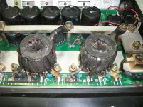
Got this amp for repair with the entire power supply blown.
I suppose gate resistors are 3R9, but i need the value of R148 and R149 (not sure about exact number as the pcb is burned). These two resistors are used between the outputs of the totem poles (BD139/BD140), to ground.
Any help would be appreciated.
I suppose gate resistors are 3R9, but i need the value of R148 and R149 (not sure about exact number as the pcb is burned). These two resistors are used between the outputs of the totem poles (BD139/BD140), to ground.
Any help would be appreciated.
Attachments
They don't appear to be burned. Desolder them and measure the resistance. The color code may be intact on the bottom if the top color bands were removed when the board was cleaned.
Thanks for the feedback. Unfortunately, the owner removed them before handing the amp to me...
He also made the mistake to install a few 100n in place of 15n on the snubber network.
I will try the 1K and see.
He also made the mistake to install a few 100n in place of 15n on the snubber network.
I will try the 1K and see.
Put the 1K resistors in place, repaired the totem pole (one set of BD139/140 was blown, as well as the 4427). A schematic of the 5k2 shows this resistors as 4k7.
Then i checked all output fets with my component tester (in circuit) and all 8 seemed ok.
I powered the amp without the ps fets and i did see the 26k square wave developing slowly.
Soldered 2 dozens of new ps fets, clamped everything back to the heatsink and tried to power the amp with my 20A bench supply. It went to protect with 3 blinks on the power led indicator.
I thought 20A was not enough for the initial current of this big amp, so i changed to a 68A power supply.
During start up, the power indicator led is blue (ok) but the amp draws around 60A+.
I am afraid on damaging something and i remove the remote after 1.5-2 seconds.
Is this normal ?
Never had the time to see it with the ps fets on.I never expected that 5 2200/200V capacitors could draw so much current while charging.
So, you say 60-65A is normal during start up?
So, you say 60-65A is normal during start up?
Last edited:
for maybe a split second, but not the 1-2 seconds you mention. Try unbolting one transformer at a time to see if you can figure out which part of the power supply is causing the issue. (just unbolt the transformer(s) from the positive bussbar).
well, no matter which transformer i unbolt its center tap from the 12V busbar, the current draw is the same.
I removed all 8 fep16dt-all checked ok.
Then bolted back all trafos and only kept the diodes out of the circuit.
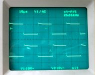
Here is the very good waveform of both sides of gate resistors ( ps fets are in place).
I removed all 8 fep16dt-all checked ok.
Then bolted back all trafos and only kept the diodes out of the circuit.
Here is the very good waveform of both sides of gate resistors ( ps fets are in place).
Attachments
Last edited:
Oh, no, current draw is about 2.3A with all diodes removed.
It seems that the primary side is working properly.
Blue led is on, as well as the clip led.
It seems that the primary side is working properly.
Blue led is on, as well as the clip led.
Okay, this is the point I would pull the 2010's out(or 2110's) and put the diodes back in. If current draw is still normal, check the signal on pins 10 & 11 of the 4011's. (looking for a good pwm signal here). If current draw is still high with the 2010's out , check the bd139/bd140 pairs and also the 15volt zeners that tie the gates to the sources. (a shorted output isn't out of the question yet though)
Another quick tip....... Look for the 3 pin connector with a jumper across pins 1&2. If you move that to pins 2&3 it shuts the 2010's off using pin 11 on them, it's an easy way to shut off the output drive for testing.
The 3 pin connector will have a couple labels on it normal run mode the jumper is in desbloq saida (Portuguese for unlock output), pins 2 & 3 set bloq saida mode (lock output).
Amp still draws lots of current either i have the IR2110 disabled or completely out of the circuit.
I will remove all 8 output fets, but i suspect a shorted trafo...
I will remove all 8 output fets, but i suspect a shorted trafo...
Hm, still there is huge current draw even with the outputs off the circuit.
Is it time to remove the rectifier diodes and measure pulses width on each of the trafos?
Is it time to remove the rectifier diodes and measure pulses width on each of the trafos?
i think what you suggest will not work, as the secondary windings are in series...
Btw, do you know what is the secondary DC voltage?
Btw, do you know what is the secondary DC voltage?
Last edited:
- Status
- Not open for further replies.
- Home
- General Interest
- Car Audio
- Stetsom 6k2