Hello,
After a failed attempt at designing a stereo tube amp with a HAMMOND 263CX, 288mA, 360VCT, it did not provide enough power to both speakers on the stereo out.
After creating a resistive divider to power the individual amp stages, I thought I would have enough power to get a strong output from the EL34s.
After designing the new power supply with a HAMMOND 273BX, 700V C.T. @ 201ma, 182VA, which is really 980VCT using 700*1.4 because of diode voltage drop (using a two-diode rectifier by the way), I am hoping to get the proper voltages that I need for the individual amp stages. Honestly not sure how the 980V supply works both ways since I think of it as 490 on the positive swing and 490 on the negative, but like, if the voltage is rectified.. it is for sure 490V? so then how does that even accomplish what I am going for which is for both channels to have adequate voltages with no under-voltages.
Here are the plate voltages that my amp should be at:
*12AT7-1/2 PreAmp = 250V
*12AT7-1/2 PreAmp = 250V
*12AT7-1/2 PreAmp = 250V
*12AT7-1/2 PreAmp = 250V
*12AT7-1/2 Kathode Phase Splitter = 250V
*12AT7-1/2 Kathode Phase Splitter = 250V
EL34 = 400V
(left) = 400V
EL34 = 400V
EL34 = 400V
(right)
EL34 = 400V
8 Tubes in total.
Each channel has 1V of signal going into preamp.
Using ot20pp output transformer (6k6ohm)
I am more than sure I have enough voltage to power 15W into each channel...(right 😅)
In the design I have done my best to include a dual gang potentiometer for both channels.. not sure if that halves the signal power but eh...I just want to make sure I am doing all of this correctly,
and sorry for such a long post, I am a novice engineer and I don't know where else to turn to, thanks in advance!
Attachments
-
 Stereo Tube Amp Self_Design.PNG65.9 KB · Views: 162
 -
 Power Tube Plate Supply.PNG14.2 KB · Views: 153
 -
 Phase Splitter Supply.PNG17.4 KB · Views: 62
 -
 PreAmp Plate Supply.PNG14.3 KB · Views: 87
 -
 Stereo Tube Amp Self_Design.PNG65.9 KB · Views: 92
 -
 Phase Splitter Supply.PNG17.4 KB · Views: 89
 -
 PreAmp Plate Supply.PNG14.3 KB · Views: 72
 -
 Power Tube Plate Supply.PNG14.2 KB · Views: 156
 -
Loadline calculator for power stages with reactive load - Vacuum Tube Amplifiers - DIY.pdf143.5 KB · Views: 62
-
Loadline calculator for concertina phase splitter - Vacuum Tube Amplifiers - DIY.pdf142.1 KB · Views: 40

What is your intended output mode? There is a 100k resistor from the screen to the anode - was that meant to be 100R for triode? If pentode was intended, then the screen will need some sort of stable supply for the screen. Also, you have a large R for the cathodes of the 6V6s, but it is not decoupled with a capacitor, which will reduce the gain.
As far as the power supply is concerned, then playing around with PSUD from Duncan Amps is highly recommended. You can test different scenarios, add loads, and so on. It forces you to consider real world questions, like what is the DCR of my transformer.
The transformer you mentioned, Hammond 263CX, only appears to have a 5V heater winding according to the specs, so that wil be an obstacle unless you have a seperate 6.3v supply. You do not have to use it with the center tap, just use a full wave bridge across the secondary, but then it will probably be too high an output voltage for your needs. Using the center tap, and it is on the low side. I suppose it is meant to provide a B+ around 250V?
Is this meant to be just a paper exercise (simulation only)?
Being frank, reinventing the wheel for a push pull amplifier is a bit of a waste of time. There are a finite number of solutions, and they are all well documented with all the information you need to be able to tweak good designs with your starting conditions. We will be very lucky if we can ever emulate the achievements of the great pioneers of tube design, so why try? Understanding what makes those designs great is the important thing.
Last edited:
Be sure to include bypass capacitors for the driver stages. If you really, really want to parallel the input stage, you probably don't really want the extra coupling capacitor - just tie the plates together. But I have no idea why you'd want to parallel the input valves.
All good fortune,
Chris
All good fortune,
Chris
Why are the input grids connected? While you have separate inputs? Disconnect the two input grids and give each grid its own grid leak (1 meg).
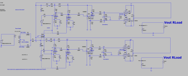
@OldHector My intended mode is pentode mode, the 100K on the screens are for dropping the voltage 2/3 of B+ so the screen has a stable supply voltage to operate as I understood, so it looks like I need to decrease my screen resistances. Okay, I should add a capacitor to decouple the cathodes, that makes sense. Also, no, this design is a gift I am making for a friend. I already have a chassis that I had my friend build, and I built up my design a few times over and could not figure out where my problem lies. I am sorry, I am not trying to reinvent the wheel, but I thought the proper way to design amps is by using a pre stage, phase splitter and power amp to drive high wattage to 8 ohm speakers.
Yes, of course.
At the node of R1 and C1, you have 490VDC
Both channels of the amp are powered from that source.
At the node of R1 and C1, you have 490VDC
Both channels of the amp are powered from that source.
@Chris Hornbeck Sorry, I don't understand, if the phase splitter already has an AC waveform coming from it, why do the driver tubes need additional input coupling caps on that node? Also, what is the harm in paralleling the valves? I thought that is how a class AB Push Pull works, thank you!
@OldHector My intended mode is pentode mode, the 100K on the screens are for dropping the voltage 2/3 of B+ so the screen has a stable supply voltage to operate as I understood, so it looks like I need to decrease my screen resistances.
As drawn you have the amp operating in triode mode, because the screens are connected to the transformer. This will work but the resistors need to be much smaller, the 100R OldHector suggests would be good. Triode mode will increase linearity but decrease output power.
In pentode the screens would be connected to a lower-voltage section of the PSU, not the output transformer.
See attached as example.
Attachments
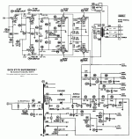
I was concerned with C11 and C4, which seem to have no purpose. Power supply points marked V3, V4, V12, V14 all need to be bypssed to signal ground.Sorry, I don't understand, if the phase splitter already has an AC waveform coming from it, why do the driver tubes need additional input coupling caps on that node? Also, what is the harm in paralleling the valves? I thought that is how a class AB Push Pull works, thank you!
The input stage is single-ended Class A and not push-pull. Paralleling here really has no purpose, and some (minor) penalties, but if you want to do it, the plate resistors should either be combined, or at least brought to the same B+ point, and the plates tied directly together.
All good fortune,
Chris
In the schematic you can see the inputs of the left and right channel are connected making it a mono amplifier. That's why I said separate the two and give each one its own grid leak. At this momnet they share the same grid leak.
@Chris Hornbeck I see now, well I thought since high voltage DC and Audio both touch the plates (regarding pre-amp input 1 and pre-amp input 2), I thought it was a good idea to decouple the DC going into the other half of the 12AT7. Then on the output, I thought that it was also a good idea to decouple the DC coming out of the pre-amps into the phase splitter which is why I had C11 and C4 there.
"Power supply points marked V3, V4, V12, V14 all need to be bypssed to signal ground." I understand why you say that, in order to smooth voltage, I have done a bit of playing around in LTSpice and at one point, I got an extremely flat DC-line coming onto the plates of the pre-amps and phase splitter, but as shown, it is not as nice anymore, thanks for the tip!
"The input stage is single-ended Class A and not push-pull. Paralleling here really has no purpose, and some (minor) penalties, but if you want to do it, the plate resistors should either be combined, or at least brought to the same B+ point, and the plates tied directly together."
I see what you mean Chris, the reason I did this is because I figure it would be good to have one pre-amp stage feed into basically another pre-amp stage which would increase my signal voltage gain. I did wholeheartedly attempt to go for the class-A stages for both channels and follow the steps along all the way down to the driver tube stages
Best,
-Sean
@Chris Hornbeck Sorry to keep bothering, but am I incorrect in my approach? If so, as I want to "stereo the amp" using say one aux cord (left, right, ground) using a dual gang potentiometer how would I do that ? In my understanding, I made a left and right amp channel yet I do want to be able to control volume at only one point (i.e. the left and right pre-amp stages) thanks again!
- Home
- Amplifiers
- Tubes / Valves
- Stereo Tube Amp Design Not Working