Stereo loudspeaker playback theory
Hello,
steric means regarding physical form, hence Stereo is about reproducing sound waves, which differ in origin, beamwidth and direction, say making it all livelier.
The simplest stereo sloudspeaker would be the Mono/Stereo one, which consists of a cardiod pointing straight ahead playing L+R and a dipole pointing to the sides playing L-R, both sources located in the same point. The last premise is practically impossible with loudspeakers, because a sound source must have some size, if it is gonna output reasonable power. Neither good is a same-sides triangle with listener and only two loudspeakers, for it would cause too much comb-filtering of L+R information. Hence we should use at least three loudspeakers. They can sit close together in a common box, if the box is used in a listening room, for reflections off walls will tell stereo, as Elias wrote there.
Elias also researched possible routings from two electrical signals to three loudspeakers and stole the following grafics
 from a Japanese. This is the simplest matrix for common-ground signals, "matrix" because it connects several in- to several outputs black-box-style. If all loudspeakers are equal, its transfer function can become described as
Ls=(2/3)*(L-R/2)
Cs=(2/3)*((L+R)/2)
Rs=(2/3)*(R-L/2) .
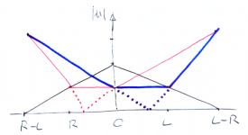
This is also known as "0.5 matrix", multiplied by a factor of (2/3) for its passivity. Following are an interpolation (solid lines) and a derivation (dots) of the positive output |U| of Ls (red), Cs (black) and Rs (blue) as a function of panning from R-L to L-R:
 Phase reverses in the aisles of the dotted lines.
Now Elias means, that such a matrix is not necessarily preserving energy. What he means is not energy but power, as power should become preserved. +++ Under Elias' criteria, the matrix described above does not preserve power. There is one set of transfer functions, which Elias considers the best, and which i steal for this post:

This set can become built with a passive common-ground matrix: Left and right path must each have an impedance four times as high as center path. Now center signals put the same electrical power into each path. Full difference signals (L-R) put approximately twice that power into each side, but those signals are rare and will never come from Vinyl and FM. Center path must have 10^(1/2)/2, approximately 4dB higher sensitivity than each side.
Uli
Hello,
steric means regarding physical form, hence Stereo is about reproducing sound waves, which differ in origin, beamwidth and direction, say making it all livelier.
The simplest stereo sloudspeaker would be the Mono/Stereo one, which consists of a cardiod pointing straight ahead playing L+R and a dipole pointing to the sides playing L-R, both sources located in the same point. The last premise is practically impossible with loudspeakers, because a sound source must have some size, if it is gonna output reasonable power. Neither good is a same-sides triangle with listener and only two loudspeakers, for it would cause too much comb-filtering of L+R information. Hence we should use at least three loudspeakers. They can sit close together in a common box, if the box is used in a listening room, for reflections off walls will tell stereo, as Elias wrote there.
Elias also researched possible routings from two electrical signals to three loudspeakers and stole the following grafics
Ls=(2/3)*(L-R/2)
Cs=(2/3)*((L+R)/2)
Rs=(2/3)*(R-L/2) .
This is also known as "0.5 matrix", multiplied by a factor of (2/3) for its passivity. Following are an interpolation (solid lines) and a derivation (dots) of the positive output |U| of Ls (red), Cs (black) and Rs (blue) as a function of panning from R-L to L-R:
Now Elias means, that such a matrix is not necessarily preserving energy. What he means is not energy but power, as power should become preserved. +++ Under Elias' criteria, the matrix described above does not preserve power. There is one set of transfer functions, which Elias considers the best, and which i steal for this post:
This set can become built with a passive common-ground matrix: Left and right path must each have an impedance four times as high as center path. Now center signals put the same electrical power into each path. Full difference signals (L-R) put approximately twice that power into each side, but those signals are rare and will never come from Vinyl and FM. Center path must have 10^(1/2)/2, approximately 4dB higher sensitivity than each side.
Uli
Attachments
Last edited:
I think he's saying that 3-channel stereo (as was used for a time) is superior to 2-channel. Fair enough; done well, it should be. A discrete centre is preferable to a phantom. Some of the 3-channel Mercury recordings were supposed to be superb. I think we're back to the perfect being the enemy of the good enough. 2-channel stereo was / is good enough for what most people want. Passively matrixing a centre-channel is easy enough, although there's usually sufficient bleed to significantly reduce the apparent L-R separation without some kind of logic to actively steer things, as they discovered in the early days of quadraphonics. Should be more easily achievable now, digitally, although it can be done with analogue, either gain-riding or something like Variomatrix or Tate Logic that actively adjusted the matrix coefficients in real time. Lynn Olson's Shadow Vector also IIRC, although that never made it to market.
In a nutshell:
* The equilateral triangle with listener and two loudspeakers should have never been promoted. It is not mono/center-compatible.
* A setup with left and right loudspeakers much closer together but radiating in different directions is more mono-compatible, and gives a stereo effect if used in a room. Some radios are set up like this, with a fullranger each at each flank pointing one to two hours to the side, often also somewhat to the ceiling.
* This setup profits from a separate center loudspeaker. Also, the equilateral triangle becomes useful, if a center loudspeaker is added.
* There is a circuit with an optimum transfer function for adressing the three loudspeakers. Elias found it.
* The three loudspeakers can be driven by a two-channel amplifier, using the less-than-perfect passive "0.5 matrix", if only equal loudspeakers are available, or Elias' optimum matrix, if loudspeakers are designed for it. Of course each loudspeaker may also receive its own amplifier for sake of flexibility.
So what are you saying that is any different than info presented here:
http://elias.altervista.org/html/SingleSpeakerStereo.html
http://www.diyaudio.com/forums/full...orations-matrixed-single-stereo-speakers.html
The matrix stuff works. I built one and when you pan the stereo image moves left to right.
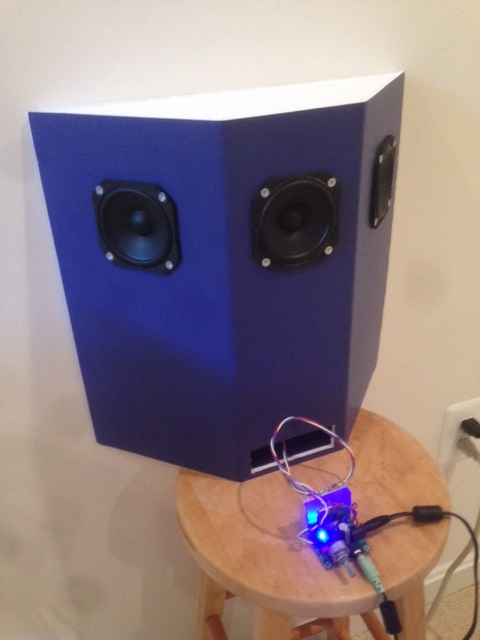
I'm using this matrix with psychoacoustic correction
http://elias.altervista.org/html/SingleSpeakerStereo.html
http://www.diyaudio.com/forums/full...orations-matrixed-single-stereo-speakers.html
The matrix stuff works. I built one and when you pan the stereo image moves left to right.
I'm using this matrix with psychoacoustic correction
An externally hosted image should be here but it was not working when we last tested it.
I reckon this is a question. Well, i combined both, saying, that Elias' best-case matrix can be founded in a passive circuit.So what are you saying that is any different than info presented here:
http://elias.altervista.org/html/SingleSpeakerStereo.html
http://www.diyaudio.com/forums/full...orations-matrixed-single-stereo-speakers.html
Why did thou choose this particular distance between left and right fullranger? Mono compatibility is best when this distance is smallest.
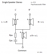
I cannot see it because i have no https. But i saw elsewhere, that you used a capacitor across the center driver. Let me elaborate on electrical filtering: If using a crossover of first order, highpass-filtering the center and lowpass-filtering each side, the beam points to the side, strengthening directivity of the back-tilted sides. This is quite contrary to a subwoofer/satellite setup, in which the sides have the trebles, and the center has the bass. Both setups are imperfect, but that is the way it is.I'm using this matrix with psychoacoustic correction
An externally hosted image should be here but it was not working when we last tested it.
I reckon this is a question. Well, i combined both, saying, that Elias' best-case matrix can be founded in a passive circuit.
Why did thou choose this particular distance between left and right fullranger? Mono compatibility is best when this distance is smallest.
I cannot see it because i have no https. But i saw elsewhere, that you used a capacitor across the center driver. Let me elaborate on electrical filtering: If using a crossover of first order, highpass-filtering the center and lowpass-filtering each side, the beam points to the side, strengthening directivity of the back-tilted sides. This is quite contrary to a subwoofer/satellite setup, in which the sides have the trebles, and the center has the bass. Both setups are imperfect, but that is the way it is.
I don't think the center is high pass filtered - the cap and resistor in series and those in parallel with center channel shunts HF to ground as determined by RC constant. This reduces the HF's reaching the center - it's a shelving filter not a low pass or high pass. Here is circuit so you can see.
Spacing on drivers is purely practical to get drivers to fit and not have magnets interfering in back and also to provide enough volume for a bass reflex alignment.
Attachments
It is a stopped lowpass, a lowpass stopped by the series resistor. Try the opposite, using a choke instead of a capacitor. That may give a different stereo effect, not less but different.
A choke there would force HF's to go through the center channel accentuating the effect of the center channel wouldn't it? I think the point of the psychoacoustic filter is to soften the HF's of the center so that the stereo localization is more dependent on the L and R channels. A choke and resistor in parallel and that in series before the center channel would be a HF shelving filter, but would also need a padding resistor to decrease the 3dB gain that the center channel has with respect to side channels as all current flows through the center channel otherwise. But that would then limit the max current that can flow through the side channels.
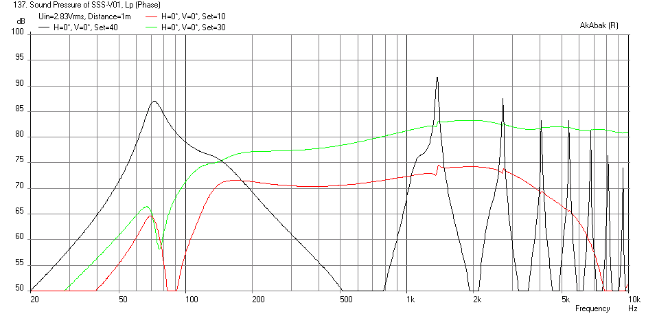
I simulated the response of the network and acoustic effect at 0 deg incidence with Akabak and it is good. You can see the falloff of the center channel.
More on the sims of the SSS here:
http://www.diyaudio.com/forums/full...xed-single-stereo-speakers-7.html#post3962898
The black is the BR output (in reality with stuffing the higher frequency peaks do not show up), the green is side, red is center channel:
Last edited:
In the trebles yes. But it would also turn phase in direction, that stereo beams are further tilted to their sides in the transition frequency range of the filter. This highpass should be stopped at -4,5dB or so, so the center loudspeaker would still get some midrange and bass.A choke there would force HF's to go through the center channel accentuating the effect of the center channel wouldn't it?
What about Embrasing Sound from Fredrik Gurnnasson? Swedish loudspeaker manufacturer NUFEELD® turns the next page in professional studio monitoring with COREGO™ - the first stereo downmix controller system based on the EmbracingSound® platform NUFEELD Stereo Downmix Monitoring Systems
Too few information there for me, pm325.
One premise of fullfilling Elias' matrix passively is to have impedance of center one fourth of each side, for example a 2 ohms center and 8 ohms sides. Then, a L=R say mono signal puts equal electric power into each loudspeaker. The second premise is to have efficiency of center at a factor of around 2.5 (+4 dB) of each side. Using one woofer each for each side and two of the same woofers in parallel for the center gives perfect impedance and quite close +3 dB efficiency.
But what were the real advantage? A "bad" setup (equilateral triangle of two loudspeakers and grown-up's head) has the first cancellation of mono at around 1.7 KHz. It is quite deep, because the head does not shade much at this frequency. Further cancellations at 1.7 KHz * 3,5,7, ... are less deep. Adding a center loudspeaker doubles frequency, at which first cancellation occurs, to 3.4 KHz. It is still deep or even deeper. (Reason: Left output is -4 dB and not shaded, rite output is -4 dB + -6 dB shaded = -10 dB and in phase, hence both sum to 0 dB. Center output is 0 dB + -3 dB shaded and out of phase, hence all sum to -11 dB. Relative to +7 dB correlated sum at lo frequencies, we have 18 dB dip at 3.4 KHz.) We have pushed cancellation out of midrange but introduced a pronounced one in presence range.
I do not design most loudspeakers for only a sweet spot, so what happens to an ear 34 cm closer to left than to rite loudspeaker, which both play a mono signal? In the "bad" case, it is cancelled at 500 Hz, quite deeply for the first wavefront, because left and rite level are still rather equal, but less deep for power response, because most home loudspeakers are still half-sphere radiators there, so reflections off walls are strong. Cancellations at 1500, 2500 and so on Hz are also strong. In the "fixed" case, cancellation frequencies double. Having three instead of two loudspeakers has further advantages in the bass range, so it is good to me.
I reasoned, that placing loudspeakers far apart from each other and running the same signal over at least two of them is always problematic. In order to double cancellation frequencies one more time, seven loudspeakers must be used. In order to faithfully reproduce two-channel stereophonics with an ensemble span of 3.4 m, say a strings quartett, for any listener located parallel to that span we need a horizontal array of say twenty 17 cm fullrangers. We do not need DSP and FIR, but i think about twenty amplifiers each fed by its special grade of xL+yR.
As this were much effort, i rather use co-incident AKA intensity and synchro-stereo, which reproduces a) a faithful mono signal and b) some stereo with the help of memory and reflective walls. Stereophonics as having been fully explored on the recording side, commercialized sixty years ago and having pushed HiFi into the mainstream is a fanal for the crapshooty of man.
Last edited:
At house, I have the same idea but in different way, wiring a third speaker between L and R channels live wires, say, you are using star and I delta wiring, but the same. In fact I do the subtraction at low level, and a post power amp.
With high quality mp3 tracks, ogg and radio or cd, the difference channel sounds great, but 128KBPS mp3's it is horrible, so an extra volume control I used.
Another difference is I use difference by the two channels, and you are adding, but the concept is similar.
With high quality mp3 tracks, ogg and radio or cd, the difference channel sounds great, but 128KBPS mp3's it is horrible, so an extra volume control I used.
Another difference is I use difference by the two channels, and you are adding, but the concept is similar.
Yea, i would want the 3 drivers the same distance from your head, and not use the cap.
If the impedance doesn't climb, use a pot to determine the value of the resistor installed around the "mono" speaker.
Moving a speaker around my tv, room reflections really change where a source seems to come from.
If the impedance doesn't climb, use a pot to determine the value of the resistor installed around the "mono" speaker.
Moving a speaker around my tv, room reflections really change where a source seems to come from.
- Status
- Not open for further replies.
- Home
- Loudspeakers
- Full Range
- Stereo playback theory