Stereo-Mode to Mono Mode on 2-CH Power Amplifier "Horch 2.4 Bal": Bridged Mode, (L + R) or (L - R) - wich Variant is this ?
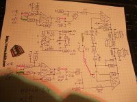
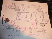
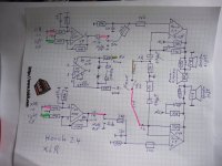
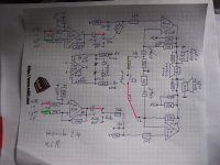
first both attachment show the schematic diagram of this stereo power amp in a professional version with a selector switch for bridged mode (mono).
A friend of me purchased it for several months.
The detailed schematic of power amp unit you will find in post #1 under
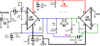
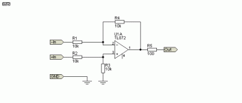
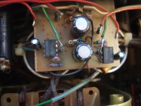
The additional input stage looks exactly than those of the third image (stolen from Rod Elliott).
Differences between 2.4 and 3.0 are only in the power supply and in the resistor values for the pos. and neg. rail to the front end.
From my view this kind of mono mode is made for an another application - maybe for summing mono amp (L+R), e. g. for mono sub woofer or even for special effects (L-R).
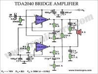
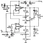
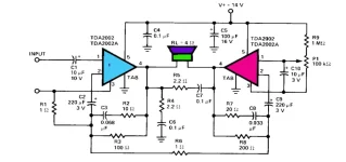
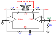
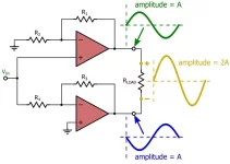
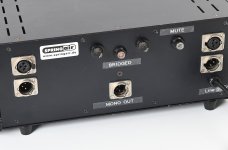
For bridged mode select on a stereo power amplifier input of one of both channels isn't in use - as I know. Fourth and fifth image show good known circuits for bridged mode.
Please let me know, what kind of mono mode was realized by use of the circuit of first both attachments - Thank you very much.
The amp was ordered here:
https://www.springair.de/de/horch-2...q5CLeCGUGDKELdpxgrooGecMnNpgEQA5a701EgD5XJhc5
P.S.: the two different NFB networks (one of which is not connected) is not an error in my created schematic - go therefore to the last both images.
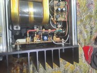
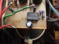
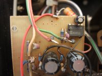
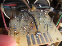
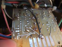
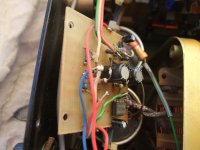
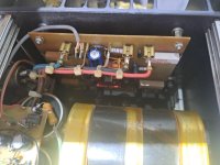
The red wire (left channel power amp unit) coming from the stereo/mono switch (in right of the grey coax input wire - last image) is connected to the 33 K resistor without 47pF in parallel in front of the blue 470 uF elcap. The second 33K resistor together with the 47pF are located in the middle of the power amp PCB - both parts are not connected as show in the simplified schematic from first both attachments.
The brown wire (right channel power amp unit) coming from the stereo/mono switch (in right of the grey coax input wire - second-to-last image) is connected to the 33 K resistor with 47pF in parallel in the middle of PCB - the 33K in front of the blue 470 uF elcap is not connected.
Whether it was really intended when designing this amplifier that on one channel the NFB resistor should be connected with and on the other without the parallel 47pF ceramic capacitor - that is the question.
first both attachment show the schematic diagram of this stereo power amp in a professional version with a selector switch for bridged mode (mono).
A friend of me purchased it for several months.
The detailed schematic of power amp unit you will find in post #1 under
Unknown reason of constant blown fuses at model 3.0s located in the 230VAC line to transformer's primary input forced me to find out the differences to the reliably operating model 3.0. The following was observed in detail:
With this power amplifier (independent mains transformers for each channel), the fuses between the mains connection and each mains transformer, located at the back plate, often blown away - sometimes only those from the right channel or only from the left channel, sometimes also those from both channels.
As a first step, I switch-on the power amplifier at another...
- tiefbassuebertr
- Replies: 7
- Forum: Solid State
Differences between 2.4 and 3.0 are only in the power supply and in the resistor values for the pos. and neg. rail to the front end.
From my view this kind of mono mode is made for an another application - maybe for summing mono amp (L+R), e. g. for mono sub woofer or even for special effects (L-R).
For bridged mode select on a stereo power amplifier input of one of both channels isn't in use - as I know. Fourth and fifth image show good known circuits for bridged mode.
Please let me know, what kind of mono mode was realized by use of the circuit of first both attachments - Thank you very much.
The amp was ordered here:
https://www.springair.de/de/horch-2...q5CLeCGUGDKELdpxgrooGecMnNpgEQA5a701EgD5XJhc5
P.S.: the two different NFB networks (one of which is not connected) is not an error in my created schematic - go therefore to the last both images.
The red wire (left channel power amp unit) coming from the stereo/mono switch (in right of the grey coax input wire - last image) is connected to the 33 K resistor without 47pF in parallel in front of the blue 470 uF elcap. The second 33K resistor together with the 47pF are located in the middle of the power amp PCB - both parts are not connected as show in the simplified schematic from first both attachments.
The brown wire (right channel power amp unit) coming from the stereo/mono switch (in right of the grey coax input wire - second-to-last image) is connected to the 33 K resistor with 47pF in parallel in the middle of PCB - the 33K in front of the blue 470 uF elcap is not connected.
Whether it was really intended when designing this amplifier that on one channel the NFB resistor should be connected with and on the other without the parallel 47pF ceramic capacitor - that is the question.
Attachments
-
 DSCF8999.JPG403.2 KB · Views: 33
 -
 DSCF8997.JPG419.1 KB · Views: 36
 -
 balanced-io-f6.gif2.9 KB · Views: 34
 -
 Simple Bridge Power Amplifier with Voltages.png15.6 KB · Views: 34
 -
 Power Amp bridge mode simplified schematic.webp21.1 KB · Views: 32
 -
 2262464b-60b0-47d7-8802-16d804da53ba.jpg69.2 KB · Views: 27
 -
 Horch 2.4 Mono.jpg117.5 KB · Views: 23
 -
 Horch 2.4 Mono front.jpg62.9 KB · Views: 26
 -
 d0c6ef74-abd9-4cf7-b68c-204cff3e609b.jpg95.4 KB · Views: 25
 -
 c392a805-c9b9-4195-8558-7cd8bc8f2580.jpg116.3 KB · Views: 24
 -
 DSCF8992.JPG419.9 KB · Views: 25
 -
 DSCF8990.JPG412.2 KB · Views: 25
 -
 DSCF8991.JPG394.4 KB · Views: 23
 -
 DSCF8993.JPG423.1 KB · Views: 22
 -
 DSCF8994.JPG379.8 KB · Views: 22
 -
 DSCF8995.JPG398.3 KB · Views: 22
 -
 DSCF8996.JPG383.2 KB · Views: 23
 -
 d0ff8c24-0bd1-45e9-b8b3-7aba7709312d.jpg64.6 KB · Views: 24
 -
 42d6f787-1f2c-4b9a-b53e-81bc4380cea8.jpg79.6 KB · Views: 28
Last edited:
After correcting two drawing errors in my created schematic diagram and comparing some well-known IC amplifiers in bridge mode I note that there is now according the good known application notes for bridge mode from IC monolithic power amplifier (chip-amps) - check out the associated attachments