Hi to every body,
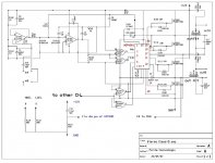
I started to desing a class-D amp(enclosed shematic). I would likte to make it stereo for full range at least 100W/4ohms. I used modified self oscillating iraud amp1. Also I choose HIP4081 instead of IR2110/2113. As I showed in the shematic, now I am using IRFP250 as output mosfets. I know they are slow, has high Qg and other worse parameters but they are working in my bread bord without heating. I am now using only one channel oscillating about 220KHz. I also tested IR2113 with same shematic but output mosfets warm up. Again I tested IR2113 with IRF540(ST) and saw high side ise still warming up. Therefore I think my last desing is ok for only 12V. For final desing, I think I need level shift and symetrical PS for input opamp and output mosfets. Now all of them running on the supply voltage of mosfet driver.
I need some help on calculating closed loop gain of this desing.
Any suggestions will help much from you experienced DIY'ers.
Regards
Attachments
Hi
I can't help you with loop gain, but I have a question.
I can't help you with loop gain, but I have a question.
What was your capacitance for upper, HI side drive?I also tested IR2113 with same shematic but output mosfets warm up. Again I tested IR2113 with IRF540(ST) and saw high side ise still warming up.
Hi Luka,
If you are asking about C8 it is 680nf. But tried 220nf and get it working without heat of high side mosfet and UVL protection of HIP4081. And now I am using 100nf+1uf(electorlitic). No problem with HIP4081 there is no heat on both mosfet. I also replaced R105 4.7K to 1K and now oscillating frequency is 330KHz and better sound.
Regards
Hi
You used 680nf with IR? That is too small. Use 22uF or more, when you will go in hard clipping you will need it. I use 100uF elco and 22uF tantal in parallel, with no heating in upper mosfet
You used 680nf with IR? That is too small. Use 22uF or more, when you will go in hard clipping you will need it. I use 100uF elco and 22uF tantal in parallel, with no heating in upper mosfet
OK
I will take this suggestion to care. But IR2113 failed in my most desings. I did some SMPS circuits with 2113 also one of my friend, who has a scop(oscilloscope), did a fulbridge SMPS with IR2113. We saw there with scop the H side mosfet is not turned off properly although there is a dead time on input stage of 2113. Therefore I used HIP4081 because, it has delay time adjusment for H and L side. You can have a look to data sheet and also application note of HIP4081 on www.intersil.com . The delay resistors with 30K there is a dealay lets say about 30-40ns or so.
Kind regards
Hi
Could you post or send me schema of that smps or amp (if you did it with IR), I'll take a look of what you used.
I have both smps and ClassD amp running with IR and that is with no problems. Didn't destroyed not even one IR.
Hip are great but limited by max voltage. If you will be making one with HIP you should look here first.
But you made this one
Didn't it work? From that picture I made my, which look pritty much the same
Hi luka,
As I saw you know what I did before. OK the scop photo belong to driver transformer version of my SMPS. But, both of them still working. The problem is IR version of my SMPS heating a bit up. Also scop result of IR version like a sinus. I enclosed the shematic of my smps' IR version. And also many thanks to you for the HIP link.
As I saw you know what I did before. OK the scop photo belong to driver transformer version of my SMPS. But, both of them still working. The problem is IR version of my SMPS heating a bit up. Also scop result of IR version like a sinus. I enclosed the shematic of my smps' IR version. And also many thanks to you for the HIP link.
Attachments
How should be my final desing?
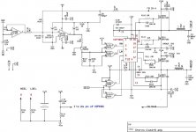
My final desing enclosed. The input section of CH-B is same with CH-A. I put there a level translator but, i think i should put a reverse polarity 1N4148 to B-E legs of Q105. +/-Vss is about 35 to 38V so the final total power supply 70 to 76V.
Ps: My circuit is not a full bridge. But ,stereo signals will be 180 degree phase angle with additional input buffers. That will give me the chance of briging two channells.
Attachments
Hi
I can tell you right now that 0.47uF is not enough, use much high C and I would use irfp450 reather then 460,rest will check later.
I can tell you right now that 0.47uF is not enough, use much high C and I would use irfp450 reather then 460,rest will check later.
Thanks Luka,
I will test boostrap cap with higher values like 47uf low ESR+100nf mylar. Also I have a working version with IRFP450 but with same boostrap cap.
Regards
I will test boostrap cap with higher values like 47uf low ESR+100nf mylar. Also I have a working version with IRFP450 but with same boostrap cap.
Regards
I forgot to say that you should use something like 47uf low ESR +100nf mylar for lower drive too. U have to have this for upper and lower side drive because you have to charge G fast from ~0 to Vcc (12V). If this is not done as it should be, fet will go in so called linear area=
I would also use 7812 instead of 15. It is enough and heat will be lower. I would remove R109 and R104 (not needed).
Other than that I don't see anything wrong for now. Did you test it? Like current limit, is feedback stable?
I would also use 7812 instead of 15. It is enough and heat will be lower. I would remove R109 and R104 (not needed).
Other than that I don't see anything wrong for now. Did you test it? Like current limit, is feedback stable?
Hi luka,
I was originally removed R104 and R109. I know that IR2113 has shimt trigerred inputs so it is correcting the worst square waves. But, I do not have scop for now. But I can say it is working better and also FB was stable when I created it.
Regards
I was originally removed R104 and R109. I know that IR2113 has shimt trigerred inputs so it is correcting the worst square waves. But, I do not have scop for now. But I can say it is working better and also FB was stable when I created it.
Regards
For this kind of things like smps's spoce is a MUST [/B][/QUOTE]
I know but, do not have. I can borrow it from a friend. But not now only weekends. Do not forget please I am a Chemist in fact 🙂.
Kind regards
I know but, do not have. I can borrow it from a friend. But not now only weekends. Do not forget please I am a Chemist in fact 🙂.
Kind regards
IR2113+HIP4081
Hey Luka and others,
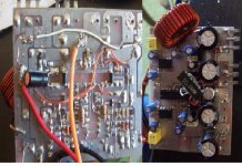
My friend could not bring the Scop this weekend because of his wery hard works on 1200VA three phase smps. Any way, I did a test pcb for HIP4081 and worked well, both channells 🙂. See the enclosed photos. I also remove 4081 and then attached IR2113 with some wring by inreasing the boostrap C to 47uf+100n. Now, This pcb is not my final desing, I did this only for test to see the layout behaviours and for final pcb. Althoug 2113 above the PCB, now only low side mosfet is heating a bit. Before this pcb I did bread board tests with 2113 and saw, H side mosfet is heating while the L side was cool. Any way, I learnt that Luka is right. I think, one can solve the heating problem of L side mosfet by desinging a good layout for IR2113.
For several hours on my test I lost 3 HIP4081. But, I get experience on this chip. I have 5 smd HIP4081 now and I will desing the input sections+4081 as a module on a thin double sided pcb.
Are there any one or any idea for layout considirations on driver modules. For eg; How should be the order of components? Hýým , my prefence ; driver module then bypass caps(2200uf)+ output filter and then the mosfets.
Hey Luka and others,
My friend could not bring the Scop this weekend because of his wery hard works on 1200VA three phase smps. Any way, I did a test pcb for HIP4081 and worked well, both channells 🙂. See the enclosed photos. I also remove 4081 and then attached IR2113 with some wring by inreasing the boostrap C to 47uf+100n. Now, This pcb is not my final desing, I did this only for test to see the layout behaviours and for final pcb. Althoug 2113 above the PCB, now only low side mosfet is heating a bit. Before this pcb I did bread board tests with 2113 and saw, H side mosfet is heating while the L side was cool. Any way, I learnt that Luka is right. I think, one can solve the heating problem of L side mosfet by desinging a good layout for IR2113.
For several hours on my test I lost 3 HIP4081. But, I get experience on this chip. I have 5 smd HIP4081 now and I will desing the input sections+4081 as a module on a thin double sided pcb.
Are there any one or any idea for layout considirations on driver modules. For eg; How should be the order of components? Hýým , my prefence ; driver module then bypass caps(2200uf)+ output filter and then the mosfets.
Attachments
Hi
Great to hear I was right I did also test my ClassD with +/-47Vdc. Still works 😀 but can't listen for long because I dont have heatsinks for power zeners. Sound is just great, deep bass, very loud.
Oh yea, just rememberd, my friend burned IR when he didn't put enough C for high side drive. To bed hi didn't saw your post earlyer.
Well put however fits your needs/skills. You can help yourself by looking on my site under My projects form my amp, and link to Baldin's page. He has HIP
Great to hear I was right
I did also test my ClassD with +/-47Vdc. Still works 😀 but can't listen for long because I dont have heatsinks for power zeners. Sound is just great, deep bass, very loud. Oh yea, just rememberd, my friend burned IR when he didn't put enough C for high side drive. To bed hi didn't saw your post earlyer.
Well put however fits your needs/skills. You can help yourself by looking on my site under My projects form my amp, and link to Baldin's page. He has HIP
Hi,
Luka I surfed on your website. Nice works and congragulations! I will ask a question about your car smps. I saw that U used a red toroidal core, ok do you know the part number of it? or what is the manufacturer? I have micrometals' T157-2 and I know it is for high frequency and initial permiabilty is low like magnetics' cooMu. I never tested my cores for power conversion but it is very similar to yours.
And I have a request, would you please e-mail me your class-d amp's shematic. I will only look, how did you achieve the adjustable dead time. Sorry I do not have much time to surf on web, I could not saw a shematic or a link to shematic did you put the shematic there?
About Baldin's amp ; he did full bridge but , I will do a half bridge stereo. So I prefer to use HIP4081(sperate inputs for each mosfet/dual half bridge driver) or two HIP2100(or IR2113) instead of HIP4080. My starting point is iraudamp1.
This will be a good class-d amp for my car.
Kind regards
- Status
- Not open for further replies.
- Home
- Amplifiers
- Class D
- Stereo Class-D amp HIP4081