I hope everyone is having an enjoyable holiday!
I have a hopefully, (final) inquiry into my first build- a stereo monoblock class A EF40/EL84, very similar to the classic Mullard 3-3.
I have built a working prototype and am hoping to reduce noise now that I have my head around the basics of building from a schematic.
I am using a PT in which I am sharing HT and filament windings between channels. I am using the 5V tap to power a GZ34 rectifier for the build. (Overkill, I am aware, and will be switching to diode FW bridge at some point)
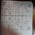
I've attached a layout of my grounding scheme. With the constraints of the PT, would I be forced to share the 0V rail between channels, or should each channel have its own 0V rail, meeting at some star around each channel's C2?
Should the chassis ground point be placed as close to the L/R channel star point as possible as well? I was looking at Merlin's grounding page and his multi-channel section seems to indicate something close to this? But it says to implement with a 'hum blocker network'. What is this?
Hopefully the diagram is legible. I appreciate any help you guys could provide!
Key:
A. Feedback network
B. Speaker output (+)
1. First stage grounds
2. Second stage grounds
I have a hopefully, (final) inquiry into my first build- a stereo monoblock class A EF40/EL84, very similar to the classic Mullard 3-3.
I have built a working prototype and am hoping to reduce noise now that I have my head around the basics of building from a schematic.
I am using a PT in which I am sharing HT and filament windings between channels. I am using the 5V tap to power a GZ34 rectifier for the build. (Overkill, I am aware, and will be switching to diode FW bridge at some point)
I've attached a layout of my grounding scheme. With the constraints of the PT, would I be forced to share the 0V rail between channels, or should each channel have its own 0V rail, meeting at some star around each channel's C2?
Should the chassis ground point be placed as close to the L/R channel star point as possible as well? I was looking at Merlin's grounding page and his multi-channel section seems to indicate something close to this? But it says to implement with a 'hum blocker network'. What is this?
Hopefully the diagram is legible. I appreciate any help you guys could provide!
Key:
A. Feedback network
B. Speaker output (+)
1. First stage grounds
2. Second stage grounds
Attachments
Assuming this stays in SE class A, the current from the supply feeding the output stage should be ideally constant (that goes away if the amp goes into clipping, but then a lot goes non-ideal if that happens!). So I think you'll find that having the supply grounds common there will be just fine since there shouldn't be any output signal flowing through the power supply.
But -- the common supply grounds at the inputs isn't a great situation and is a recipe for ground loop noise problems (hum due to safety ground currents). It can be fixed by separating the L and R channel input circuit grounds from safety/main ground by some small resistors (say 5 to 15 ohms). Those shouldn't upset the biasing of the input stage, but would greatly decrease any noise current flowing in the input ground shields/returns. TubeCAD has several articles about his "Unbalancer" which is a variation of this concept, and I did a circuit analysis with some typical valuesto help understand why it works. It does work, and really well. Some amps of mine went from unlistenably hummy to silent background. See below about where to put the resistors.
But -- the common supply grounds at the inputs isn't a great situation and is a recipe for ground loop noise problems (hum due to safety ground currents). It can be fixed by separating the L and R channel input circuit grounds from safety/main ground by some small resistors (say 5 to 15 ohms). Those shouldn't upset the biasing of the input stage, but would greatly decrease any noise current flowing in the input ground shields/returns. TubeCAD has several articles about his "Unbalancer" which is a variation of this concept, and I did a circuit analysis with some typical valuesto help understand why it works. It does work, and really well. Some amps of mine went from unlistenably hummy to silent background. See below about where to put the resistors.
Last edited:
Thanks for the reply. That seems to make sense. The input sockets are isolated from the chassis. As of now, the chassis ground is at the star with the PT CT, filament CT and reservoir cap (-).
I'm wondering if the grounds from the two channels should be on seperate buss runs from the first filter cap (C2) to V1's grid-to-ground resistor? I guess that's what I was trying to illustrate- should both channels share a common ground buss between them, with all of V1 (L) and V1 (R)'s grounds, etc. tied together? (Sort of mirrored, as illustrated in accompanying drawing)
Or, should the ground buss split after the reservoir cap, going to each channel's RC filter for V2? And then, does this mean the ground buss to chassis connection should be here where the teo branches intersect?
The Mullard 44 seems to do it the former way, with the shared 0V split right after the reservoir cap. Is this the best way to reduce noise?
Either way would work. You have a common PSU, and somewhere in your system the input grounds will be joined together, so you can't actually separate that which is already joined. The thing with grounds is to think about where the currents flow. Use whatever best fits your physical layout.
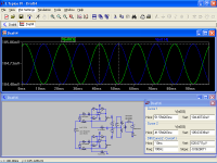
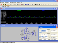
This illustrate pretty well the issue.
i) Two input grounds connected to the same ground point on the PSU via L4 and L5 (just 50nH !)

ii) Two 10 Ohm resistors, HBRL and HBRR, between signal ground and PSU ground

In this case, this represents an improvement in hum reduction of about 56dB.
i) Two input grounds connected to the same ground point on the PSU via L4 and L5 (just 50nH !)
ii) Two 10 Ohm resistors, HBRL and HBRR, between signal ground and PSU ground
In this case, this represents an improvement in hum reduction of about 56dB.
Attachments
I have a decent bit of experience with the 3-3. Be sure that input cap is there to maintain the grid leak bias, then use a pair of shorting plugs at the inputs of the amp.
Without doing this, you may think your amp is noisy when it may not be at all.
Without doing this, you may think your amp is noisy when it may not be at all.
Thanks again for the replies.
I've got both input caps in place and I use shorting plugs to test all my amps. 🙂
I suppose I'll just experiment with jumpers for the best spot from 0v to chassis. My feeling is noise might be reduced if I place it closer to where the two channel grounds merge together before meeting power ground.
The only remaining issue to work out is whether there is an advantage in noise level in keeping the two 47uf decoupling caps grounds tied together as seems to be common with the earlier layout documentation I can find. (Can caps and the like)
But it seems like it would make more sense to have the second decoupling cap tie to V1's grounds and the one closer to the reservoir, (C2) to V2's grounds.
On that note, I imagine the entire circuit would benefit from additional smoothing or another RC filter- perhaps before V2's screen or T1?
I would get rid of the hum different way, and not use negative feedback at all.
of course going to just a simple polarized plug is an option.
of course going to just a simple polarized plug is an option.
I would get rid of the hum different way, and not use negative feedback at all.
How do you propose to resolve the issues of damping and distortion without feedback?
Should the chassis ground point be placed as close to the L/R channel star point as possible as well?
You're refreshingly asking the right questions. Folks so often just draw a ground symbol and call it a day.
To add one thing to the great advice already posted, you might consider separating signal ground(s) from safety Earth ground. Current practice is to couple them with back-to-back rectifier (big) diodes, often doubled by a bridge rectifier wired funny.
All good fortune,
Chris
<snip>
of course going to just a simple polarized plug is an option.
This is actually not a very safe suggestion - should there be an insulation failure in the primary wiring to chassis, then chassis and I/0 could be at mains voltage with the most convenient path to ground through an end user or the shield of an RCA cable to a properly grounded component, otherwise everything ends up hot. (Pretty exciting either way)
A PE protects against AC mains shorts to chassis through a defective switch or wiring, transformer primary to core shorts, and shorts from primary to secondary windings with a reference to ground.
It also violates the spirit and probably the letter of the forum's safety rules.
Even though you use a 'ground bus', always aim to make local star connections on that bus. A local star is the single point for a local circuit to connect. Eg. The f/b ground connects to the same point as the associated cathode resistor. As DF96 points out, try and visualise each circuit sections local current loop.
Since the OP is in the USA, safety Earth is possible, therefore mandatory. It's not for you; it's for your children, pets, and other worthies.
Good discussions are sprinkled around this forum and are concentrated in Bob Cordell's excellent amplifier book (top recommendation for all kinds of reasons). He also discusses the issues around input signal grounds, Zobels, etc. in practical and useful ways.
All good fortune,
Chris
Good discussions are sprinkled around this forum and are concentrated in Bob Cordell's excellent amplifier book (top recommendation for all kinds of reasons). He also discusses the issues around input signal grounds, Zobels, etc. in practical and useful ways.
All good fortune,
Chris
- Status
- Not open for further replies.
- Home
- Amplifiers
- Tubes / Valves
- Stereo Class A monoblock smoothing cap grounds