I got tired of cobbling together resistors to attenuate amplifier signals when doing distortion measurements. For low-level measurements, having a rats nest of parts and wires on the bench was bad from a noise standpoint as well.
So I decided to put together a fully differential stepped attenuator. I wanted:
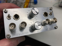
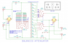
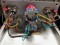
The first picture shows the completed unit in a small aluminum case. The second shows the schematic with resistor values and the third shows the internal (somewhat messy) point-to-point wiring. The resistors are mounted directly on the switches.
For the shunt resistors, I used 1%. For the input and series string resistors, I used 0.1% in order to keep common-mode errors low in balanced mode.
Note that the attenuator has an in-built 3 dB insertion loss due to the shunt arrangement, so I have to mentally add in -3 dB when doing measurements. Not a big deal.
The front panel was designed in KiCad and sent off to JLCPCB. I specified aluminum for the substrate. They charged me US$0.50 each (plus shipping) and had them to me in a week. This is a great way to get nice-looking panels done on the cheap.
Cheers!
So I decided to put together a fully differential stepped attenuator. I wanted:
- Either fully differential or single-ended use (switchable)
- XLR (mini) and BNC connectors
- Coarse and fine adjustment
The first picture shows the completed unit in a small aluminum case. The second shows the schematic with resistor values and the third shows the internal (somewhat messy) point-to-point wiring. The resistors are mounted directly on the switches.
For the shunt resistors, I used 1%. For the input and series string resistors, I used 0.1% in order to keep common-mode errors low in balanced mode.
Note that the attenuator has an in-built 3 dB insertion loss due to the shunt arrangement, so I have to mentally add in -3 dB when doing measurements. Not a big deal.
The front panel was designed in KiCad and sent off to JLCPCB. I specified aluminum for the substrate. They charged me US$0.50 each (plus shipping) and had them to me in a week. This is a great way to get nice-looking panels done on the cheap.
Cheers!
Attachments
Last edited:
The panel option from JLBPCB looks really interesting.
The impedances look low enough that you won't get serious response issues. The easy balanced/unbalanced is a nice trick, especially if you have an isolated floating source.
The impedances look low enough that you won't get serious response issues. The easy balanced/unbalanced is a nice trick, especially if you have an isolated floating source.
I wonder how you ordered the panel on JLCPCB. Aluminum substrate, white PCB color -> black silkscreen, no solder mask, removed order number? Thanks!
Exactly right - except I forgot to say no order number. 😀
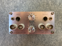
The aluminum looks nice, but you could also specify a white solder mask on the front with black lettering.
Here is a better picture of the panel.
The aluminum looks nice, but you could also specify a white solder mask on the front with black lettering.
Here is a better picture of the panel.
Attachments
Last edited:
For the shunt resistors, I used 1%. For the input and series string resistors, I used 0.1% in order to keep common-mode errors low in balanced mode.
Cheers!
What about freq. response and required freq. compensation cap's?
Hp
The frequency response is pretty much ruler-flat to 20 Hz to 20KHz at all attenuation steps. This is using short, low capacitance cables and a low impedance output from my sound card. I think that since the resistors are all relatively low value, there is not much roll-off in the audible band.
For my use case, it is a moot point regardless, since I tend to do a calibration loop with the attenuator, notch filter, and soundcard in series, then switch to a low distortion oscillator (Victor's) feeding a DUT and subtracting out the calibration anomalies.
For my use case, it is a moot point regardless, since I tend to do a calibration loop with the attenuator, notch filter, and soundcard in series, then switch to a low distortion oscillator (Victor's) feeding a DUT and subtracting out the calibration anomalies.
- Home
- Design & Build
- Equipment & Tools
- Stepped Differential Attenuator