okay (thanks again for al the insights) - here is a summary of what I currently have and what needs to be done:
Current setup
To be done
Will that do the trick?
Current setup
- AD1865 with i/v resistors
- 6DJ8 preamp with 100k stepped attenuator
- 6V6 Push Pull Power amp with 100k input impedance
To be done
- Add capacitors in the signal path at the output of the dac
- Add 1M resistors to ground between these capacitors and the output jacks on the dac chassis
- Add 1M resistors to ground at the output of the 100k stepped attenuator (between the attenuator and the preamp pcb)
Will that do the trick?
Last edited:
No need for resistors at the DAC output to ground, but they won't do any harm. The attenuator will provide a DC ground at this point. Resistors here will reduce clicks if you plug in a source while the system is live, which is bad practise.
You do need a coupling capacitor at the attenuator output. The 1M resistor on its own will do nothing. I have said this before but you don't seem to get it. You need caps on both sides of the attenuator.
Happy Christmas!
You do need a coupling capacitor at the attenuator output. The 1M resistor on its own will do nothing. I have said this before but you don't seem to get it. You need caps on both sides of the attenuator.
Happy Christmas!
OK no probs.
Now - in terms of determining the value of the capacitors to put between the attenuator and the preamp PCB, what is a value that is "safe"? I don't know the input impedance of the preamp, but I do know that the coupling caps in the preamp are 2.2uF and the input impedance of the power amp is 100K.
Would 1uF be a good starting point?
I just caught your thread. I usually use resistor built attenuators and I have never had any pops or other problems even with 50k or 100k pots. Assuming that your pot is a make before break type ( I would double cheak that ) and your sources are clean of dc you could still be getting a small amount of dc in your switch if you have one too many earth connections around your pot or pre amp which would allow an earth loop to form. This would be my guess. I would check that everything only connects to earth once ( check this by doing continuity checks with the equipment switched off using a multi meter ) before you decide you need to insert capacitors in the circuit.
Don
Don
Have you read the thread? He has DC from his source, and grid current from his load. Hence the advice to add caps on both sides.I just caught your thread.
problem solved!
Added 1uF caps AFTER the attenuator with 1M resistors to ground. Then tested with a source that had caps, and also the ad1865 dac (no output caps) and the results were perfect in both cases, no clicks or pops whatsoever when turning the attenuator and also no discernible side effects (no loss of bass, nor apparent SQ).
The dc offset from an ad1865 appears to be be negligible (2-3mV) so the caps after the attenuator are doing the trick perfectly.
Thanks to all who helped out!
That's because the equipment after the attenuator is sending DC back down the interconnect.
It's the Power Amplifier that needs to be corrected.
It's the Power Amplifier that needs to be corrected.
That's because the equipment after the attenuator is sending DC back down the interconnect.
It's the Power Amplifier that needs to be corrected.
It's probably the preamp circuit (the system runs from source to attenuator to preamp to power amp).
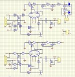
Attached is the schematic of the preamp - can anyone see an obvious reason it may be leaking dc back into the attenuator?
Attachments
Hi
"just caught your thread.
Have you read the thread? He has DC from his source, and grid current from his load. Hence the advice to add caps on both sides. "
I always read all the thread before replying. I am pointing out that there is another possible explanation for the switching noise ( presumably caued by dc at the contact ) that has not so far been considered in the thread.
I do not claim to know the actual cause of the switching noise - that can only be determined by looking at the whole set up in detail - we do not know that. However if I am correct the solution to stopping the switching noise is a simple on. It is worth checking.
Don
If you don't have any luck, you might try using an RDAC based attenuator. There are no contacts or wipers, no mechanical connections to pop or scratch. Just seems a better way to do it. It's also simple, at least in this implementation is just two chips:
In this implementation, the attenuation step sequence is provided in firmware, so it's perfectly logarithmic, not an approximation like potentiometers have. That circuit has six pots and several switched lines so you can have have up to five sources (e.g. tuner, turntable, CD, etc.). You can use all of the pots for audio control, or if you just want stereo, you'll have unused pots that can be used to drive a display. It's a simple circuit but still has lots of flexibility.
You can do it yourself - firmware and proto circuit - or if you're less of a programmer and more of a solder slinger, contact Bruce Heran (OddWattAudio.com) or Uriah Dailey (BuildAnAmp.com) for kits or preprogrammed chips. Then it's a simple matter of hooking up two chips and a handful of wires, nothing to it.
OK, but you said that you assumed that "sources are clean of dc" when we already knew that both his source and load had DC problems. The best way to fault-find is to fix the obvious known faults, then see if anything more needs to be done after that. Your suggestion might have been useful at the second stage, but we still hadn't taken the first stage at that point.AMV8 said:I always read all the thread before replying.
I understand he has now added caps at both sides, and the problem has been solved.
I understand he has now added caps at both sides, and the problem has been solved.
I've added caps AFTER the attenuator (between the attenuator and the preamp pcb) which has stopped the popping/clicks when rotating the attenuator.
However the mystery noted by AndrewT still remains - why/how was the preamp circuit leaking dc back into the attenuator?
You have a connection straight to a valve grid? You will have some grid current. How much depends on many things such as bias, valve ageing, exact valve metals used.
Appears minimal - I measured the dc at the end of the caps and it reads as 4.6v on one channel and 4.4v on the other...lucky because the caps I used are 63v 1uF, so should be safe.
Do you mean V or mV? Even mV is enough to make clicks. Microvolts standing DC would be minimal. A microamp of grid current across 10k gives 10mV of DC, so you would need grid current down in the nA region to avoid caps here.
Sorry - yes, mV, my error.
What is odd is that the 2mV from the AD1865 dac w/ passive i/v resistor doesn't cause clicks but the grid current dc does! Unless the caps after the attenuator are now blocking all the dc before the preamp pcb....
What is odd is that the 2mV from the AD1865 dac w/ passive i/v resistor doesn't cause clicks but the grid current dc does! Unless the caps after the attenuator are now blocking all the dc before the preamp pcb....
Last edited:
The 2mV from the source is attenuated by the attenuator. The 4mV from the load is not.
Actually, not quite true. The 4mV from the load will be attenuated a bit too by the load imposed by the attenuator output impedance, but this will disappear/change between switches (depending on MMB or BBM).
Actually, not quite true. The 4mV from the load will be attenuated a bit too by the load imposed by the attenuator output impedance, but this will disappear/change between switches (depending on MMB or BBM).
Last edited:
look at your schematic.
The J1PIN1 is connected via R11 & R22 To the grid.
That is the problem. There is no DC blocker in that path.
It could be DC leaking back.
But much more likely is the effect of variable source resistance affecting the grid voltage.
When the attenuator is between switch positions it is either open circuit or a pair of parallel resistors.
The Grid sees R22+R13 if the source is open circuit
or
grid sees r22 + { r13//(r11+Rs) } if Rs is connected.
These two grid conditions will result in a change in output voltage.
The switched attenuator changes instantly from one grid bias condition to another and back again. Hence the click, or pop, or bang goes your speaker.
Using a resistive track that gradually changes the source resistance seen by the grid is almost as bad. The only bit missing is the instantaneous change in output voltage during the switching.
The Pre-amp should never have been designed with a DC coupled input feeding direct to the grid. As I said much earlier: The designer should be strung up, drawn and quartered.
Last edited:
Thanks Andrew - excellent insight, what would you recommend doing to rectify the design flaw? Or, do you think the solution implemented thus far is about as good as it gets.
On another note, I notice that as I turn the pot there is a persistent hum that gets louder with the variable gain applied - it is definitely not a ground loop hum as it is completely gone when the pot is at its minimum. What could cause this kind of humming?
On another note, I notice that as I turn the pot there is a persistent hum that gets louder with the variable gain applied - it is definitely not a ground loop hum as it is completely gone when the pot is at its minimum. What could cause this kind of humming?
- Status
- Not open for further replies.
- Home
- Source & Line
- Analog Line Level
- stepped aattenuator - stop pops