We have a lot of posters here that are working with SMPS to get higher voltage from 12V or 24V battery sources. Here's a thread where we can discuss ideas, schematics, theories, and more when it comes to making Step-Up SMPS.
12V SMPS for car or vehicle audio
12V SMPS Power Inverters for 120V (or 240V)
12 or 24V SMPS for Uninterruptible Power Supplies
MOSFETS, Diodes, Toroids, Transformers, Capacitors and other components used to build such DIY projects.
12V SMPS for car or vehicle audio
12V SMPS Power Inverters for 120V (or 240V)
12 or 24V SMPS for Uninterruptible Power Supplies
MOSFETS, Diodes, Toroids, Transformers, Capacitors and other components used to build such DIY projects.
I just got working a small, experimental 12V SMPS controlled by a TL494 IC.
What I made to work on the SMPS....
I made a small PCB just for a TL494 and associated components only. It's designed to directly drive MOSFETS when testing and building SMPS circuits. The 494 drives two 33 ohm resistors which drive two separate pairs of complementary MJE15034/35 BiPolar transistors, to provide two High Current outputs so when testing if I have a fault, I won't fry the TL494IC chip! (it's in a socket just in case I do have to change it) It also uses small pin terminals so I can just "plug in" rT and cT for different values. Also has a trimmer pot (68K) to adjust Dead Time. Circuit has 4 wires total it uses.... Two for 12V power, and Two wires for MOSFET gates.
I drove a pair of NTY100N10's (no heatsink) with 1ohm gate resistors, and testing with a 150W load, they didn't even get warm. Now I have to finish the rest of it, will post pics later.
Good luck so far, have to find some good high voltage fast diodes for the output.
Having the seperate timing circuit to drive MOSFETS makes it easier to design and test before actually having to completely build the whole SMPS and timing circuits together. It's basically a complementary square wave generator.
Any comments or ideas feel free to post.
How does the output circuit on an AC power inverter work? How does it simulate sinewaves without dissipating a lot of power? I've searched on the internet to be run around in circles.
They use PWM. Or they just output square waves.EWorkshop1708 said:How does the output circuit on an AC power inverter work? How does it simulate sinewaves without dissipating a lot of power? I've searched on the internet to be run around in circles.
I wanted to add about transformers......
A lot of SMPS use toroids to step up the 12V to 60V or more.
I'd like to substitute with available PSU transformers.
Also a lot of computer Power Supply use E-I ferrite transformer to step down from 120V to 12 and 5V.
Now if you drive these transformers backwards, they work great as a step-up. Just drive the 5V or 12V "secondary" as a primary with 12V power. The 120V side becomes your new secondary side.
With Push-Pull, Using a transformer from a 550W computer PSU I got +/-90V (180V) when driving the 5V coils, and +/-35V (70V) when driving the 12V coils. The 120V side had a center tap with no lead, so I soldered a wire to it, and was able to get split voltages.
Have any of you here used these transfomers before? If I can get decent power out of one, I may use these on a few projects instead of toroids.
Any tips on building better SMPS is welcomed.
GOOD NEWS!
For you folks designing really HIGH POWER SMPS.....
Here's a treat!
250A 100V MOSFET TO264
http://ixdev.ixys.com/DataSheet/99022.pdf
And Digikey has em!
http://search.digikey.com/scripts/DkSearch/dksus.dll?Detail?name=IXTK250N10-ND
Better than the OnSemi NTY100N10
For you folks designing really HIGH POWER SMPS.....
Here's a treat!
250A 100V MOSFET TO264
http://ixdev.ixys.com/DataSheet/99022.pdf
And Digikey has em!
http://search.digikey.com/scripts/DkSearch/dksus.dll?Detail?name=IXTK250N10-ND
Better than the OnSemi NTY100N10
Dear EWorkshop1708 .
Last year i been *sort.of* doing the same .
Although i used a different oscillator i builded a board with sg3525 for experimental purposes .
Its a great way to learn and understand one of the basic parts of a smps .
(when i have to be honest that oscillator is by now abused for several projects with succes)
Cause it turned out to be very usefull knowledge and is used as a basis for a.o. an ac-ac chopper ,pwm regulated dc load and a inverter for dad's camper.
Now on to the next topic .
Making a sinewave inverter .
In the proces of dad's camper inverter i made a few trials ,modified sinus (normal 50 hz transformer 50 hz square waves with +-20-30 % dutycycle) ,but also sinewave inverter .
You should have a look around on the web about magic or true sine .
There are several good sites with information but it requires programmingskills .
Basicly like Star822 already said they use pwm and filter a sinewave out of it .
That (basic) setup is smps - pwm generation with a microcontroller - low pass filter .
Now the last and maybe the most important i might say today (sorry its valentine )
I learned a lot from reading Eva's comments and discussions .
Yes Eva honor to the ones that deserve it ,your reply's and comments impressed me and gave me more insight , i learned a lot from you (and the rest over here ofcourse).
Do yourself a pleasure and listen when they explain you something .
It might save you some black spots on your desk .
Good luck
EWorkshop1708
black spots on the desk............LOL
So far I haven't burnt anything up yet 😀 😱
Using a computer PSU just in case a fault happens, a lot safer than car battery, however I'm starting to push it to it's limits and just might use the battery anyway
Also 2 questions:
How BIG of a Toroid core can be used for SMPS at high frequencies? Does a bigger core give me more power without saturation??? I'm wanting to try and wind a huge Toroid that's 4-5 inches in diameter to get some high power. 😀
Also, how do I figure out what frequency I'm running? I got my SMPS running good right now with 2.2K ohm rT and 0.0022 uf cT I'm using EI transformer from PC Power supply. Getting +/- 35V
Eva said:In 12V push-pull applications, a pair of IRF2907Z beats one of devices in every respect.
I'm tempted to get some of these, they have awesome specs for TO-220 parts.
EWorkshop1708 said:
Also, how do I figure out what frequency I'm running? I got my SMPS running good right now with 2.2K ohm rT and 0.0022 uf cT I'm using EI transformer from PC Power supply. Getting +/- 35V
Your running at around 30KHz (you didn't list the dead time resistor so I don't know for sure)
The fourmula is in the datasheet, bottom of page 4.
I took some time to look up some docs for the TL 494/594 (not SG3525) and when I followed the equations in the datasheet, it says I'm running 103khz.
And if I raise my cT to 0.0047 uf, I'll be near 50khz.
I'm about to do a test again soon, nearer completion. I just built an IC socket, and most parts to support TL494/594 now on the same PCB as the SMPS. I also used overrated MJE15034/35 Bipolar drivers for dependability to drive the MOSFETS.
I also added snubbers as they are recommended here. It ran fine before without them, I'll see how it runs now with them soon. I used 10W 50 ohm/0.1uf snubbers.
I also just got some new 30A 200V and 600V Ultrafast Diodes to make rectifiers with. 😀
I still have my 494 testing circuit, and I can stick the output wires in the IC socket pins to test with it before inserting the IC itself.
What about using feedback? Is it necessary for car amp? I'm thinking of making this SMPS have trimmer to vary the voltage just to experiment. Right now, it's set to run wide open.
EWorkshop1708 said:I took some time to look up some docs for the TL 494/594 (not SG3525) and when I followed the equations in the datasheet, it says I'm running 103khz.
And if I raise my cT to 0.0047 uf, I'll be near 50khz.
Thats odd, when I put your values in ( 2K2 for Rt and 2n2F for Ct) I get 186 KHz Osc., (93 KHz switching)
When I put in 2K2 for Rt and 4n7F for Ct I get 101 KHz Osc. and 50.5 KHz switching (which is what you got).
It's up to you if you want feedback, the supply in the car doesn't change that much, it's more complex though. Although if you set the error amp at a gain of 1 and use a trimmer to change it you could have an ajustable rails (not regulation).
hi EWorkshop1708, very interesting, exactly what I m looking for, when u would show us some schematics, can any one give me a name of a BJT for totem pole for use with SG3525 to hard switch (~ 100ns ) eight IRF3205, would BD139/140 work, thanks for sharing ur experience with us,
EWorkshop1708 said:I just got working a small, experimental 12V SMPS controlled by a TL494 IC.
What I made to work on the SMPS....
I made a small PCB just for a TL494 and associated components only. It's designed to directly drive MOSFETS when testing and building SMPS circuits. The 494 drives two 33 ohm resistors which drive two separate pairs of complementary MJE15034/35 BiPolar transistors, to provide two High Current outputs so when testing if I have a fault, I won't fry the TL494IC chip! (it's in a socket just in case I do have to change it) It also uses small pin terminals so I can just "plug in" rT and cT for different values. Also has a trimmer pot (68K) to adjust Dead Time. Circuit has 4 wires total it uses.... Two for 12V power, and Two wires for MOSFET gates.
I drove a pair of NTY100N10's (no heatsink) with 1ohm gate resistors, and testing with a 150W load, they didn't even get warm. Now I have to finish the rest of it, will post pics later.
Good luck so far, have to find some good high voltage fast diodes for the output.
Having the seperate timing circuit to drive MOSFETS makes it easier to design and test before actually having to completely build the whole SMPS and timing circuits together. It's basically a complementary square wave generator.
Any comments or ideas feel free to post.
I made something similar too....
I used a TL494 and a pair of buffers for complementary outputs for driving fets. it also has on board IRFZ34 fets for test driving cores.
it has sockets for Ct. Rt is a 50k pot (measure resistance after getting satisfactory operation to get Rt value) it also has pwm adjustment from 0-100%
@Areza.
bd 139/140 will do fine i guess .
Let me quote Mr. Pressman here .
To drive a gate to 10 volt "on" level in the time Tr the required current I1 is :
I1 = Cgs x Dv / Dt = Cgs x 10 / Tr
However in driving the gate up 10 volts ,the drain turns on and drops from Vdc to Vds (on) voltage (which will be for simplicity be taken as ground .
Thus as the top end of Cgd moves down Vdc its bottom end moves up 10 volt .
The current required to do so is .
I2 = Cgd x Dv / Dt = Cgd(Vdc+10)/Dt
Ig = I1 + I2
(Cgs = C gate - source Cgd = C gate - drain
The kudo's go ofcourse to Mr. Pressman .
If you like i can send you the layout i made last year (for sg3525)
I chosen the sg3525 because of the output stages capable of driving mosfets without external transistors .
Its by no means meanth as a finished smps/inverter but for understanding the oscillator and experimenting it worked fine for me .
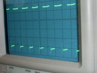
(i'll add some of the pictures i have from the output signals)
The pictures is taken with 310 volt on the output ,maximum load i had attached was 400 watt .)
bd 139/140 will do fine i guess .
Let me quote Mr. Pressman here .
To drive a gate to 10 volt "on" level in the time Tr the required current I1 is :
I1 = Cgs x Dv / Dt = Cgs x 10 / Tr
However in driving the gate up 10 volts ,the drain turns on and drops from Vdc to Vds (on) voltage (which will be for simplicity be taken as ground .
Thus as the top end of Cgd moves down Vdc its bottom end moves up 10 volt .
The current required to do so is .
I2 = Cgd x Dv / Dt = Cgd(Vdc+10)/Dt
Ig = I1 + I2
(Cgs = C gate - source Cgd = C gate - drain
The kudo's go ofcourse to Mr. Pressman .
If you like i can send you the layout i made last year (for sg3525)
I chosen the sg3525 because of the output stages capable of driving mosfets without external transistors .
Its by no means meanth as a finished smps/inverter but for understanding the oscillator and experimenting it worked fine for me .
(i'll add some of the pictures i have from the output signals)
The pictures is taken with 310 volt on the output ,maximum load i had attached was 400 watt .)
Attachments
hi walkura , thanks for the infos , i love to have the layout , so i can improve my one, i need to hard switch eight IRF3205, can i use one set of BD139/140 for 8 IRF3205 ,
Hi Areza.
In the zipfile i attached you have the layout i used last year .
Its basicly just a oscillator where i connected the transformer over the edge of the pcb.
(i monted copper terminals for amp plugs there)
(afterall it was intended for learning)
The second ic is a microcontroller i used for monitoring the battery voltage etc. just forget about that or cut it off)
The layout is made in Proteus designsuite .
There is a potentiometer for dutycycle and 1 to adjust frequency .
You might have to place snubbers (i just soldered those over the mosfets)
From what i read i guess you want to drive 2 x 4 mosfets .
So far i driven on this configuration 2 x 2 mosfets without much problems .
My guess is that 2 x 4 won't be much of a problem with BD 139/140 .
Some day soon i will make a new version (lately i been doing some new trials with this plate but there's a new one to come)
Just a few minutes ago on the thread of archimedus Pushpull i posted a schematic that might interest you .
Seen the amount of power you try to achieve it might be good as information .
Just drop in if you have questions
Have a nice eve & Good luck .
Attachments
Short but sweet for now .
I did a quick search for the Russian schema .
Its NOT the one i had in mind but its close 🙂
Better pay some attention here cause its a mix of 3 topology's 🙂
For the 100 Ampere model .
They use a small top222 powersupply as bias supply .
They use a uc 3845 supply to drive a 2 transistor forward converter.
Just look a little around between those links .
Cxema = schema
You will find several versions from 40 to 160 Amperes .
http://y-u-r.narod.ru/Svark/svark.htm
Have fun .
Ok then last one for now .
This is the Russian schematic i meanth .
I loved it when i first saw it ,now this is creative (and evil) use of parts 🙂
http://imajr.com/Original.aspx?Id=spawark1100_393678
This is the Russian schematic i meanth .
I loved it when i first saw it ,now this is creative (and evil) use of parts 🙂
http://imajr.com/Original.aspx?Id=spawark1100_393678
- Status
- Not open for further replies.
- Home
- Amplifiers
- Power Supplies
- Step-Up SMPS Thread