I've been working on the compensation for a classic three stage SS PA amp. I seem to have eliminated ringing and over shoot, although I see this funny little squiggle on the lagging edge of the wave form. It's worse on the negative side, and barely presents itself on the positive side. I'm having trouble figuring out where it arises from. The rise rate of the amp in simulation seems to be about 15V/us. The bandwidth is set for about 200kHz.
Here are some screen shots of the step response:
The full step:
The positive leading edge:
The negative lagging edge:
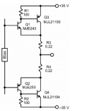
The circuit is simple and minimal:
Here are some screen shots of the step response:
The full step:
An externally hosted image should be here but it was not working when we last tested it.
The positive leading edge:
An externally hosted image should be here but it was not working when we last tested it.
The negative lagging edge:
An externally hosted image should be here but it was not working when we last tested it.
The circuit is simple and minimal:
An externally hosted image should be here but it was not working when we last tested it.
Last edited:
I worked it out. Here's 20 kHz square wave to 20Vpk driving 4u7 in parallel with 4 ohms.
Now, if the as-build circuit performs as well as the sim...
An externally hosted image should be here but it was not working when we last tested it.
Now, if the as-build circuit performs as well as the sim...
Your CFP output stage has big attempt to thermal run away. I find a better configure for CFP stage. It has better current control with R3 & R4 in the diagram.
You may add 10 ohm resistor to the emitter of Q1 & Q2 to improve stability of CFP. There are tons of local feed back there. Sometimes it is unstable.
You may add 10 ohm resistor to the emitter of Q1 & Q2 to improve stability of CFP. There are tons of local feed back there. Sometimes it is unstable.
Attachments
I reverted the output stage back to full complementary because that configuration allows current in the driver stages to stay on at all times, and so eliminates cross over distortion from arising there.
Also I omitted the over-current protection circuitry from the model while I work the the kinks out of the rest of the design.
Also I omitted the over-current protection circuitry from the model while I work the the kinks out of the rest of the design.
- Status
- Not open for further replies.