Hello,
my amp goes in protect-mode. Just connected power + & - & REM -> same state.
I measured the voltage up to the primary winding. After this nothing due to protect.
I dismantled the amp and checked every transistor and they are all ok.
The only bad thing i see that the legs of the transformer (2 on primary and 1 on secondary winding) are a little dark and smells very light burnt.
At this point im stuck. Any help is welcome also circuit diagrams... 🙂
Thank you!
Check the DC voltage on all of the bridging speaker terminals as you power up the amp. Does any channel pulse high or low as the amp attempts to power up?
Post the DC voltage on all of the pins of the power supply driver IC.
IC#
Pin 1:
Pin 2:
Pin 3:
Pin 4:
Pin 5:
Pin 6:
Pin 7:
Pin 8:
Pin 9:
Pin 10:
Pin 11:
Pin 12:
Pin 13:
Pin 14:
Pin 15:
Pin 16:
IC#
Pin 1:
Pin 2:
Pin 3:
Pin 4:
Pin 5:
Pin 6:
Pin 7:
Pin 8:
Pin 9:
Pin 10:
Pin 11:
Pin 12:
Pin 13:
Pin 14:
Pin 15:
Pin 16:
The DC Voltage on all of the pins of the power supply driver IC.
IC# SG3525AP
Pin 1: 0 V
Pin 2: 0 V
Pin 3: 0,009 V
Pin 4: 0 V
Pin 5: 13,68 V
Pin 6: 0,008 V
Pin 7: 0,019 V
Pin 8: 0 V
Pin 9: 0 V
Pin 10: 0 V
Pin 11: 0 V
Pin 12: 0 V
Pin 13: 0,005 V
Pin 14: 0 V
Pin 15: 0,005 V
Pin 16: -0,196 V
IC# SG3525AP
Pin 1: 0 V
Pin 2: 0 V
Pin 3: 0,009 V
Pin 4: 0 V
Pin 5: 13,68 V
Pin 6: 0,008 V
Pin 7: 0,019 V
Pin 8: 0 V
Pin 9: 0 V
Pin 10: 0 V
Pin 11: 0 V
Pin 12: 0 V
Pin 13: 0,005 V
Pin 14: 0 V
Pin 15: 0,005 V
Pin 16: -0,196 V
Was the amp in protect mode when you measured the voltage?
Are you sure you have the pin numbering correct?
Are you sure you have the pin numbering correct?
yes, it was in protect-mode...
numbering according to the datasheet
1 16
2 15
3 14
4 13
5 12
6 11
7 10
8 9
numbering according to the datasheet
1 16
2 15
3 14
4 13
5 12
6 11
7 10
8 9
Are you sure that you have the orientation of the IC right? Pin 5 has 13v on it. I'd expect to see that on pin 13 instead.
it is the 16(narrow)-type, but i do not see the dot in the corner like in the picture in the datasheet... anyway when i flip the values pin 13 has 13,68V... 🙂
SG3525AP - 16(narrow) - SO16:
IC# U2
Pin 1: 0 V
Pin 2: 0 V
Pin 3: 0 V
Pin 4: 0 V
Pin 5: 0,005 V
Pin 6: 0 V
Pin 7: 0,005 V
Pin 8: -0,196 V
Pin 9: 0 V
Pin 10: 0 V
Pin 11: 0,009 V
Pin 12: 0 V
Pin 13: 13,68 V
Pin 14: 0,008 V
Pin 15: 0,019 V
Pin 16: 0 V
SG3525AP - 16(narrow) - SO16:
IC# U2
Pin 1: 0 V
Pin 2: 0 V
Pin 3: 0 V
Pin 4: 0 V
Pin 5: 0,005 V
Pin 6: 0 V
Pin 7: 0,005 V
Pin 8: -0,196 V
Pin 9: 0 V
Pin 10: 0 V
Pin 11: 0,009 V
Pin 12: 0 V
Pin 13: 13,68 V
Pin 14: 0,008 V
Pin 15: 0,019 V
Pin 16: 0 V
there are two paths:
--------------------------------------
1st path (from power supply to PIN 15):
PS (+) --> R1 to R4 in parallel --> Q26 + Q27 in parallel --> PIN 11
PS (+) --> R5 to R8 in parallel --> Q7 + Q16 in parallel --> PIN 14
Q16 + Q26 in parallel --> C30 --> C31 --> PIN 15
--------------------------------------
2nd path (from temp.sensor - "evaluation area"):
R251 (temp. sensor to enclosure, has 5,2 kOhm ?!?) --> PIN 15
U15 (Motorola LM3580, PIN 8) --> PIN 15
--------------------------------------
every R (resistance) tested --> OK, because same values in Ohm.
every Q (transistor) tested --> seem OK
I am afraid, that we come back to the windings... if the amp has temp. evaluation problems i should see the red & green lights and not just the red one (i assume that the green light is OK... 🙂 )
--------------------------------------
1st path (from power supply to PIN 15):
PS (+) --> R1 to R4 in parallel --> Q26 + Q27 in parallel --> PIN 11
PS (+) --> R5 to R8 in parallel --> Q7 + Q16 in parallel --> PIN 14
Q16 + Q26 in parallel --> C30 --> C31 --> PIN 15
--------------------------------------
2nd path (from temp.sensor - "evaluation area"):
R251 (temp. sensor to enclosure, has 5,2 kOhm ?!?) --> PIN 15
U15 (Motorola LM3580, PIN 8) --> PIN 15
--------------------------------------
every R (resistance) tested --> OK, because same values in Ohm.
every Q (transistor) tested --> seem OK
I am afraid, that we come back to the windings... if the amp has temp. evaluation problems i should see the red & green lights and not just the red one (i assume that the green light is OK... 🙂 )
Last edited:
just found a third big loop...
i will post it little later...
green light checked... it is working 🙂
i will post it little later...
green light checked... it is working 🙂
here comes the third and last path:
--------------------------------------
3rd path (from U16, PIN 10 or 14 (bridged, PIN 1 and 5 also) to U2, PIN 15):
U16: 339, ST 93K021 (14 pins - plastic micropackage SO)
found the datasheet by searching "LM339 datasheet" ?!?
*Rxxx: these parts are just with one leg in path. Can i skip writing them down if the path is not broken?
U16, PIN 10 or 14 --> R219 --> *R217 --> *R216 --> Q43 --> *D17 --> *R215 --> *R214 --> *R212 --> U2, PIN 15
----------------------------------------
from the 6 channel amp sections in parallel to U16, PIN 10:
--> R211 --> *R212 --> Q42 --> *R213 --> R250 --> U16, PIN 10
-----------------------------------------
should i write down all paths to U16?
I appreciate the time you took doing this but I'm looking for components that are directly connected to pin 15. Do any pins of the two small transistors near the 3525 have any legs that are directly connected to pin 15?
Can you post a photo of the bottom of the board covering the area from the components around the 3526 to the terminal blocks. If the original photos are of higher resolution, please email me both photos.
babin_perry@yahoo.com
babin_perry@yahoo.com
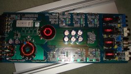
please take/download the high-res photo on the first page...
when zooming in i can read/see everything...
the 3525 is sitting in the area above the print of the pcb called "top side"...
PIN 15 is the second from top on the right side...
thank you again for your support!
bottom photo is on the way
when zooming in i can read/see everything...
the 3525 is sitting in the area above the print of the pcb called "top side"...
PIN 15 is the second from top on the right side...
thank you again for your support!
bottom photo is on the way
Last edited:
- Home
- General Interest
- Car Audio
- STEG 75.6mx in protect