stability of entire shebang depends of current reference ...... and I simply didn't had a nerve to wrestle neither with discrete option nor with thermally dependent LM334, for instance
have no idea/knowledge of any other ready made CCS solution, being cheaper, even if slightly worse
LT3092 itself isn't that expensive, when you take in account how important role of it is, though I admit it i PITA when you need to get 100+pcs, whatever way of buying it I choose
so, Bob Pease's idea of augmenting LM334 with PNP bjt is tempting ...... need to check it this days ....... main reason not the price of ideal part, but availability issues
......
Also interesting how most expensive part is none of the transistors or "active parts" or anything, but the lt3092 current source (5-10$/pc).. (ok, if we ignore the 2SK2145)
.....
when dealing strictly with DIY builds, meaning - nowI'mgoin'tobuidlmebestampintheworldoneandonly, specific parts can be in PITA category, but in most cases you need some luck and some spare pocket money, to obtain even most tricky ones ... patience being most prominent factor
now, when you're Big Boy as Papa, life is ( well deserved with hard work) much easier - you have agenda, whatever kind of money you invest it'll be well spent .... life is easier when you go spending and everyone knows you're buying high volumes
but when you're thinking about small series, while still being Peanut category, life is much more complicated - you need quantities but you can't buy significant ones to get proper price breaks, while in Era of Spanish Fle World is gone Berserk, there is no logic in parts stock nor in regular top-ups
go figure
so, entire rant regarding LT3092 availability; they can be bought (sorta) but still have some in biggie case (SOT223), not so eager to get small ones (SOT23-8) .....
no substitute for so great part, fist possible candidate being LM334
catch 22 - that one being more temperature sensor than proper CCS, having significant positive TempCo, be it result of device dissipation OR increase of ambient temperature; what you see as "67.7mV" is rising as hell
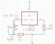
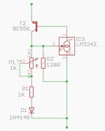
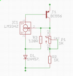
see attached picture
left one is basic arrangement
mid one - Bob Pease's solution for part dissipation, practically few uA going through LM334, thus TempCo practically nonexistent
bummer, but our regular FW format amp is heater itself, you can count on 25C temperature rise every time when Thingie is powered On...... poor 3legged bugger is heated outside, it doesn't matter that there is no heat inside
so, time to include TempCo trick from Datasheet, slightly cheating - we still need to have trrimpot in adequate position, thus being able to slightly alter C trhough CCS, setting amp Iq
so, besides Bob's trick, added one more resistor and 1N148 diode; diode TempCo , following shown resistors ratio, practically nulling chip temperature slide

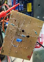
did tried entire thingie on bench, as Ikebana prototype, with lab supply and whatnot of instruments
verified basic arrangement, my own breath is making it berserk, at least comparing to LT3092; simple calculus involving change of mosfet Ugs and taking xconductance, no go, big time
then tried Pease trick - slightly calmer, but still breath/finger touch sensitive; logical .......
added diode trick, connected contact Temp. meter to LM334 case, heating it to 50C with SMD breezer ......... hehe, now we are talkin'!
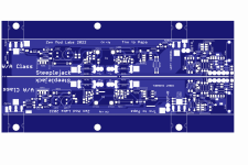
time to put it on Steeplejack , instead of LT3092
verified basic arrangement, my own breath is making it berserk, at least comparing to LT3092; simple calculus involving change of mosfet Ugs and taking xconductance, no go, big time
then tried Pease trick - slightly calmer, but still breath/finger touch sensitive; logical .......
added diode trick, connected contact Temp. meter to LM334 case, heating it to 50C with SMD breezer ......... hehe, now we are talkin'!
time to put it on Steeplejack , instead of LT3092
Attachments


Last edited:
Result - from 25C of chip temp, heated with SMD gun to 50C or so, even slliiiiight neg. TempCo, nothing to worry about
Conclusion - I have solution for situation of temporary LT3092 extinguish
money (difference) for part is not in game, considering superior stability with LT3092; but with this solution, I got it damn near
though, with IXYS pucks, no way that I'm going even to try anything else than LT3092, call me Chicken ZM
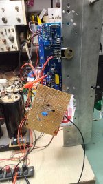
shown existing block with LT3092 and replacement block with LM334
Conclusion - I have solution for situation of temporary LT3092 extinguish
money (difference) for part is not in game, considering superior stability with LT3092; but with this solution, I got it damn near
though, with IXYS pucks, no way that I'm going even to try anything else than LT3092, call me Chicken ZM
shown existing block with LT3092 and replacement block with LM334
Attachments
Result - from 25C of chip temp, heated with SMD gun to 50C or so, even slliiiiight neg. TempCo, nothing to worry about
Conclusion - I have solution for situation of temporary LT3092 extinguish
money (difference) for part is not in game, considering superior stability with LT3092; but with this solution, I got it damn near
though, with IXYS pucks, no way that I'm going even to try anything else than LT3092, call me Chicken ZM
shown existing block with LT3092 and replacement block with LM334
Just don’t use 1N4148 for the final build. For the better results,1N457 is recommended.
Here's why.
yeah, read that in datasheet of LM334
tried, no difference in current and temperature range of interest
tried, no difference in current and temperature range of interest
Practice trumps theory. 👍yeah, read that in datasheet of LM334
tried, no difference in current and temperature range of interest
Understood, and i agree with the reasoning. Availability is problem more than price yea...and considering what is being built, price is a non-issue.
I like your experiment with discrete, that pretty much solves availability for all the lt3092 amps with common IC for the most part....no excuses anymore, very good stuff ZM
I like your experiment with discrete, that pretty much solves availability for all the lt3092 amps with common IC for the most part....no excuses anymore, very good stuff ZM
......
shown existing block with LT3092 and replacement block with LM334
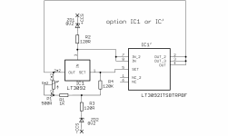
silly ZM, made significant error drawing LM334 schmtc for screenshot, above in post #24
it's proper as this ( LT3092 repeated too, for clarity) :
Attachments

..... which leads me to some thinking about unification
dilemmas, possible solutions/options
-LT3092, as superior, due to market troubles must include both cases on pcb - both SOT233 and SOT23-8
-LM334 with all gizmos to make it constant enough, seems to be not superior but more than good enough
so, future amp pcbs, why not making CCS in form of small Daughter board ..... so making just one final iteration of main pcbs, using CCS momentarily available/on hand
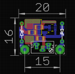
Daughter board :
-soldered parallel to main pcb when main pcb is mounted on L bracket horizontally in amp, so trimpot screw pointing up;
-soldered at 90deg angle to main pcb when main pcb mounted flat on heatsink, so trimpot screw pointing upward
soldering stubs for Daughterboard - leftovers of 3A (1N540x) diodes (1.3mm Dia) or equal solid core wire, if there are no leftovers
huh .......
LT3092 Daugtherboard:
dilemmas, possible solutions/options
-LT3092, as superior, due to market troubles must include both cases on pcb - both SOT233 and SOT23-8
-LM334 with all gizmos to make it constant enough, seems to be not superior but more than good enough
so, future amp pcbs, why not making CCS in form of small Daughter board ..... so making just one final iteration of main pcbs, using CCS momentarily available/on hand
Daughter board :
-soldered parallel to main pcb when main pcb is mounted on L bracket horizontally in amp, so trimpot screw pointing up;
-soldered at 90deg angle to main pcb when main pcb mounted flat on heatsink, so trimpot screw pointing upward
soldering stubs for Daughterboard - leftovers of 3A (1N540x) diodes (1.3mm Dia) or equal solid core wire, if there are no leftovers
huh .......
LT3092 Daugtherboard:
Attachments


Zehr gut! Basically bulletproof'd against apocalypse now, all parts comfortably gettable well into future..
Brainstorm idea thing...what if the mainboard still has all the stuff for LT3092 like previously (it is not that much components size-wise), but also has the two solder points for +CSS and -CSS on which you'd solder the LM334 board if you dont want to go LT route (in this case then builder leaves whole LT3092 section empty on the mainboard and puts on LM334 daughterboard and off to the races).
Advantages:
- only one daughter board then, since LT3092 is intergrated already
- only alteration from previous ver's would just be the +-CSS connection points (to use with new daughter board)
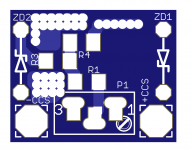
no difference, in current return - what is important is taken care of - damping 120R resistors on top and bottom of CCS, serving as suppressing/antiosci. elements, as always close and integral part of CCS itself, so situated on Daughterboard
yeah, leaving one on main pcb and adding "just" wirepads for second, in form of Daughterboard - that was first idea
though, original pcb being most crowded exactly in that area, taking care of big enough copper pad for LT (no dissipation as critical, but ZM is OmniOCD) and whatnot - there is simply no space for wirepads .......... component count is small, but - as I said - area is fully crowded
besides, in way as I did it in the end, that is a way to always have trimpot screw following sunshine, so why not

Δ mV/°K of 1N4148 @ 1 ma is ~2.1mV/°K, slightly different compared to ~2.5mV/°K of 1N457.Just don’t use 1N4148 for the final build. For the better results,1N457 is recommended.
To minimize temperature effect of LM334 using 1N4148, a simple recalculation to determine value of R2 (of post#31) may be modified to :
(R1 + P1) = 8.25 * R2
R2 = 0.1486 V / ISET
So for 1mA :
R2 ~ 150 Ω (148.6 Ω calculated)
R1+ P1 ~ 1235 Ω (1225 Ω calculated) hence 1 kΩ for R1 and 500 Ω for P1 is good.

Which means 1N4148 can be used with R2=150E and LM334 will maintain or minimise thermal drift? Or is 1N457 still superior? I have it in my Element14, cart, ready to place an order. Thanks.
- Home
- Amplifiers
- Pass Labs
- Steeplejack ..... or how F8 met Mighty Babelfish M25 (& Schade)