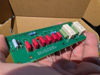
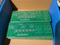
I'm at a point where i am confident in this board design, at least for the SRD-7. I have minimal interest in commerce and i know there's not much money in this, but i did order a stack of 30 boards.
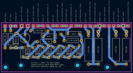
It's largely a distillation of the official schematic for the SRD-7 MkII and modifications recommended by a few other tinkerers, so i don't really take credit for the circuit itself, just the board design. I'm using the same kind of cockroft-walton voltage multiplier as Stax used for the bias supply. Ballast resistors are 4.7M. Optional bias reserve caps moved to *before the ballast resistor. Noisy PTH devices replaced by regular power resistors. Room enough to reuse vintage resistors or to use whatever boutique power resistors you want.
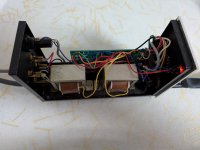
It can also be used to convert a self-biased energizer to wall-powered bias. It *may be able to give you a self-pro-bias energizer out of an old SRD-4 but I haven't tested this yet and i may need to revise the design for that. I also haven't tested fitment in the SRD-6 yet and at a minimum it needs another hole drilled, or some foam mounting tape, as i hadn't realized that the mounting brackets in the SRD-6 are 100mm center to center.
I've also tested it in an SRD-5.
In an SRD-7, you basically desolder wires from the original board and solder them to the same position on the new board. The exception is that I've provided a position for a fuse when adding wall power (or upgrading an SRD-5).
The BOM is less than $10 from mouser for one board.
$10 plus postage, will come in a padded envelope with a short length of 2.85mm black 3d printer filament that you can use to plug the center hole on the socket you upgrade to high bias.
Edit: For no tracking number CONUS first class, $2 + 1 for up to two additional boards. If you want a tracking number, lmk and i will see what we can figure out but rates are redonkulous
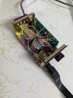
If i have enough parts left over when i am done testing and upgrading the energizers i have on hand, i may offer one or two fully populated boards. I Really don't want to upgrade your energizer for you. The SRD-7 pictured below is actually an earlier prototype layout, for full disclosure.
It can also be used to build a fully DIY energizer with high-quality transformers from Lundahl or similar, or whatever push-pull output transformers you got (must have a center tap on the HV side).
I'm not tryin'a be in business, I'm just proud to have produced it. You don't have to spend hundreds of dollars on a direct-drive amp for any modern staxen - you can modify a good old SRD-7 and use it with whatever amp you got. Dip a toe in and see what 'stats are like. Even the ancient ones are good, and yes the modern ones are mostly better.
Standard disclaimers apply - uses wall power and generates high voltages so exercise due care. Applying too high of a bias voltage to your electrostatic headphones may destroy them.
Edit 5/15/25: updated BOM to reflect more appropriate tvs diode
It's largely a distillation of the official schematic for the SRD-7 MkII and modifications recommended by a few other tinkerers, so i don't really take credit for the circuit itself, just the board design. I'm using the same kind of cockroft-walton voltage multiplier as Stax used for the bias supply. Ballast resistors are 4.7M. Optional bias reserve caps moved to *before the ballast resistor. Noisy PTH devices replaced by regular power resistors. Room enough to reuse vintage resistors or to use whatever boutique power resistors you want.
It can also be used to convert a self-biased energizer to wall-powered bias. It *may be able to give you a self-pro-bias energizer out of an old SRD-4 but I haven't tested this yet and i may need to revise the design for that. I also haven't tested fitment in the SRD-6 yet and at a minimum it needs another hole drilled, or some foam mounting tape, as i hadn't realized that the mounting brackets in the SRD-6 are 100mm center to center.
I've also tested it in an SRD-5.
In an SRD-7, you basically desolder wires from the original board and solder them to the same position on the new board. The exception is that I've provided a position for a fuse when adding wall power (or upgrading an SRD-5).
The BOM is less than $10 from mouser for one board.
$10 plus postage, will come in a padded envelope with a short length of 2.85mm black 3d printer filament that you can use to plug the center hole on the socket you upgrade to high bias.
Edit: For no tracking number CONUS first class, $2 + 1 for up to two additional boards. If you want a tracking number, lmk and i will see what we can figure out but rates are redonkulous
If i have enough parts left over when i am done testing and upgrading the energizers i have on hand, i may offer one or two fully populated boards. I Really don't want to upgrade your energizer for you. The SRD-7 pictured below is actually an earlier prototype layout, for full disclosure.
It can also be used to build a fully DIY energizer with high-quality transformers from Lundahl or similar, or whatever push-pull output transformers you got (must have a center tap on the HV side).
I'm not tryin'a be in business, I'm just proud to have produced it. You don't have to spend hundreds of dollars on a direct-drive amp for any modern staxen - you can modify a good old SRD-7 and use it with whatever amp you got. Dip a toe in and see what 'stats are like. Even the ancient ones are good, and yes the modern ones are mostly better.
Standard disclaimers apply - uses wall power and generates high voltages so exercise due care. Applying too high of a bias voltage to your electrostatic headphones may destroy them.
Edit 5/15/25: updated BOM to reflect more appropriate tvs diode
Attachments
Last edited:
I wanted to mention, regarding this blog:
https://www.linearz.com/stuff/transforming-the-stax-srd-7/
Since this board is designed to mimic the original board in an srd-7, moving the termination resistors to before the series resistors to improve linearity is done the same way. Swap the "pink input" and "yellow input" with their respective yellow transformer leads. On non-SRD-7 builds of course the wires will be different colors, but you should be able to figure things out anyway. by referencing the official schematics that stax provided.
I don't have opinions about his filter mods, but i understand that they're about taming the treble of the SR-X Mk3 without using eq in your source.
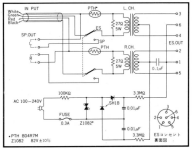
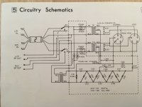
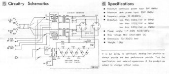
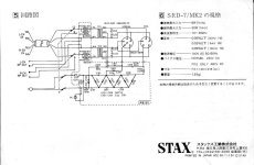
I've attached all of the official stax schematics i have. I would still love to see official schematics for either the 6/sb or the normal bias 7/sb, which appear to have the same board.
I've ordered a high voltage / high impedance probe so i can figure out what bias voltage is being actually created. It's possible that the zener may need to be upgraded to the P6KE120 (or ZY120 for self-biased). I say this out of confusion with the way that, for example, the SR-3 is referred to as having 200v bias and the SR-X and other newer normal bias 230v, but the 5, 6, and 7 NB explicitly use a bidirectional zener with a working voltage of about 83v, and double it, and you'd think that would mean they are getting about 165v. And then the SB energizers have an additional stage of multiplication.
I can measure the voltage at the zener no problem on wall-powered energizers. My DMM is probably loading down the multiplier when measured before the ballast resistor. My self-biased build rapidly discharges into the DMM. Thus, a probe with a 1-gigohm resistor in it is on its way to me.
https://www.linearz.com/stuff/transforming-the-stax-srd-7/
Since this board is designed to mimic the original board in an srd-7, moving the termination resistors to before the series resistors to improve linearity is done the same way. Swap the "pink input" and "yellow input" with their respective yellow transformer leads. On non-SRD-7 builds of course the wires will be different colors, but you should be able to figure things out anyway. by referencing the official schematics that stax provided.
I don't have opinions about his filter mods, but i understand that they're about taming the treble of the SR-X Mk3 without using eq in your source.
I've attached all of the official stax schematics i have. I would still love to see official schematics for either the 6/sb or the normal bias 7/sb, which appear to have the same board.
I've ordered a high voltage / high impedance probe so i can figure out what bias voltage is being actually created. It's possible that the zener may need to be upgraded to the P6KE120 (or ZY120 for self-biased). I say this out of confusion with the way that, for example, the SR-3 is referred to as having 200v bias and the SR-X and other newer normal bias 230v, but the 5, 6, and 7 NB explicitly use a bidirectional zener with a working voltage of about 83v, and double it, and you'd think that would mean they are getting about 165v. And then the SB energizers have an additional stage of multiplication.
I can measure the voltage at the zener no problem on wall-powered energizers. My DMM is probably loading down the multiplier when measured before the ballast resistor. My self-biased build rapidly discharges into the DMM. Thus, a probe with a 1-gigohm resistor in it is on its way to me.
Attachments

For boutique builds, Sonic Craft stocks fully non-magnetic resistors in most of the needed values. Their non-magnetic 4.7M for the ballast resistor is only available in 1/2W which is probably fine, but I'm unsure how important the voltage rating is - theirs is only rated to 500v.
The 5w power resistors will run you $8/ea from them, fwiw.
The 5w power resistors will run you $8/ea from them, fwiw.