Hey all!
I have a small problem that has recently been noticed.
Whenever I turn my headphone amp off, a very loud pop happens. I'm concerned this is going to break or prematurely wear components/headphones.
Would supplementing the standard schematic with an addition similar to the circuit shown here -> https://www.idec.com/language/english/AppNotes/Relays/contact_circuit_protection.pdf
...for the CR circuit across the switch solve my problem?
Probably so, but in practice just the capacitor across the switch works well enough.
Use a 0.02uF-0.047uF "X" type of capacitor (very important, since it's across the AC line).
Be sure to use an adequate voltage rating part as well.
Use a 0.02uF-0.047uF "X" type of capacitor (very important, since it's across the AC line).
Be sure to use an adequate voltage rating part as well.
Last edited:
Rayma,
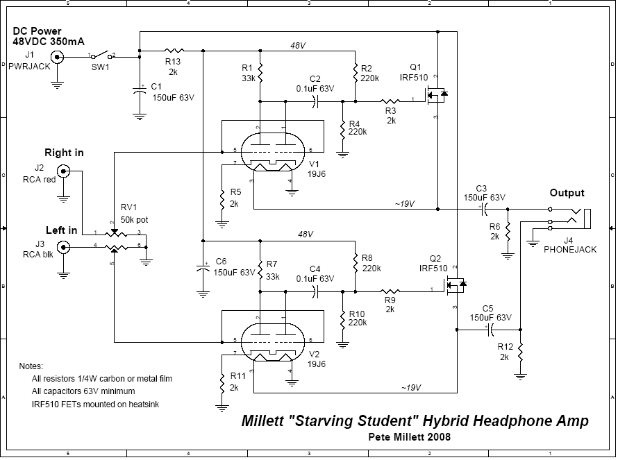
In this instance the schematic and supplied voltage is 48VDC, not AC. I will keep that in mind though and find a suitable capacitor to match.
In this instance the schematic and supplied voltage is 48VDC, not AC. I will keep that in mind though and find a suitable capacitor to match.
the schematic and supplied voltage is 48VDC, not AC.
That's a bit high for many switches, which could be damaged by that much DC voltage.
Could you switch the power elsewhere (and leave that switch on), like at a wall outlet?
Last edited:
This has nothing to do with de-bouncing the power switch with a cap.
This is common and normal for capacitor coupled SE Class A headphone amps. It happens on turn on too. The way to avoid this requires that you don’t plug in your headphone until several seconds after amp is powered up and to remove them before powering down. It has to do with the coupling cap charging up and discharging when the DC level is applied/removed. It takes a finite time for the resistor connected to the output (in parallel with headphones) to discharge the cap. A relay controlled by a supervisor circuit that provides a delay after turn on and instantly disconnects upon turn off, preferably with a delay on main amp power will stop this. But that is complicated.
You can reduce the effect by decreasing the value of the discharge resistor to drain the cap faster. But that imposes a lower impedance load to your amp and distortion will go up.
The nominal value of the discharge resistor is probably 1k on the amp, maybe make it 270ohms. You might be ok if you have 250ohm headphones as overall impedance is about 120ohms but the turn off thump will be about 4x less powerful. Hope that helps.
AY! That's super helpful knowledge, much appreciated.
To be clear though, because I'm not exactly understanding you, which resistor specifically are you referring to. Do you mean to say add the resistor and cap as suggested above, or are you saying modify a resistor value on the base schematic?
Sorry, I'm just very new and want to perfectly understand what you are saying before I go ripping things apart.
PS- I've attached the output of the schematic just for clarity.
Attachments
You can reduce the effect by decreasing the value of the discharge resistor to drain the cap faster. But that imposes a lower impedance load to your amp and distortion will go up.
Could also use a "make before break" DPDT switch to throw a lower resistance across R6 before Vcc is removed.
I mean make R2 and R6 smaller. They are nominal 2k here, make them say 470ohm to be 4x faster discharge.
xrk971,
Thanks! I'll give that a shot, hopefully with good results 🙂
jackinni
What effect would the DPDT switch serve in this situation?
Would you just run a line from the R2 and R6 directly to ground in the 'off' terminal state?
Wouldn't all applications still cause an issue unless I was instantaneous with the switch?
You just flip the switch to disconnect your phones before you turn on and before you turn off. Basically same as what a smart microcontroller and relay would do. Just easier than physically pulling the headphone jack out of the amp.
jackinni
What effect would the DPDT switch serve in this situation?
Would you just run a line from the R2 and R6 directly to ground in the 'off' terminal state?
Wouldn't all applications still cause an issue unless I was instantaneous with the switch?
"Make before break" -- the load resistor would discharge the capacitor more quickly (milliseconds) before the power is disconnected.
- Home
- Amplifiers
- Headphone Systems
- Starving Student Pop when turned off