i think it is a good thing to keep baffle size (really all panels) as small as possible to keep panel noise to a minimum, offset drivers lowers the diffraction ripple at least on axis and it can also be used to time align the drivers somewhat
Yes, but do you like line symmetry or do you like point symmetry? 😉If baffle edges are rounded to mitigate edge diffraction why can't drivers be centred. I like symmetry. 🙂
Measure any dome tweeter with a round faceplate in free air or mounted in the center of a round baffle. Even if the edges of such a round baffle are beveled, response on axis sucks. And there is no cure for that.
Non-symmetrical placement correctly applied only leads to a flatter on axis response (because the phase cancellations are spread over a wider frequency area), off axis behavior is worse and non-symmetrical. There is a tradeoff in that. I cannot think of any explanation though why 'imaging' would be worse.Jeff Bagby once stated that he felt non-symmetrically placed drivers caused the speakers to not image well.
So, not a fan of waveguides?or mounted in the center of a round baffle.
You COULD...
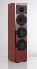
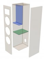
Construct a low edge diffraction distortion cabinet like 3-attached examples
Select small frame 1" tweeter and cut faceplate for shortest C-to-C spacing with midbass
Use a 6" midbass which can cover ~80Hz to 1,700 - 2,000Hz in a SEALED volume because...
Use two 8" woofers in SEALED volume for best transients and modest 11" - 12" baffle width
Hello everyone
reinforcing the line of thought of Line Source, I would recommend taking a look at the Visaton project "La Belle" that follows exactly these guidelines but with a much simpler to build and also sealed cabinet.
Stay safe, best regards
Carlos
Attachments
Non-symmetrical placement correctly applied only leads to a flatter on axis response (because the phase cancellations are spread over a wider frequency area), off axis behavior is worse and non-symmetrical. There is a tradeoff in that. I cannot think of any explanation though why 'imaging' would be worse.
My guess is it comes from reflected energy. That mid / tweeter frequencies are launching differently due to asymmetry and therefore this is somehow diffusing the image.
design by starting with the front baffle dimensions.
It's clear that looks play a big part in many builders' decisions, but taking sound as the first criterion, where do you start?
Start with science. For example, you'll use your speakers in a room so you'll have a room transition from ray acoustics to modal. Thus, your main channels don't need to play down into the modal range and won't supply much benefit if they do. That will have a large impact on your baffle design because you aren't forced to place a large driver on your baffle.
Another consideration is the size of the driver vs the frequency range you'll play through it. When the physical length of the soundwave is larger than the diameter of your driver it will tend toward omnidirectional. If you play frequencies shorter than the diameter of your driver they will begin to become more directive. Some designers do that intentionally use that as part of their design. So if you wanted a larger diameter speaker so that it beamed you'd wind up with a larger baffle size. Or, you could use a larger baffle size to make a smaller driver more directive at a lower frequency because you sort of increased the driver diameter by surrounding it with baffle that reflects the frequencies forward instead of wrapping around back.
Then you also want to consider where you will place your speakers because you'll want to understand how boundaries and room reflections will impact the sound.
Then, you'll want to think about what kind of music you like and what is most appealing to you. You might like lots of room reflections or you might prefer to minimize them. That will also impact your baffle size/shape like if you start wanting waveguides.
I think the big problem is that room reflections have a major impact on our perception of sound quality, and people have different preferences for the types of room reflections they prefer.
But I'd say the baffle choice comes later down the road after you've figured out what you want your speaker to do inside a room and what your personal preferences are.
Lol. Every enclosure is a waveguide 😛So, not a fan of waveguides?
Might as well be that, with symmetrical placement, the resulting on-axis ripple leads to a perception of ‘image’.My guess is it comes from reflected energy. That mid / tweeter frequencies are launching differently due to asymmetry and therefore this is somehow diffusing the image.
I'd think that smaller width baffles might actually be tougher to get right as it pertains to diffraction. Reasoning would be that "local", to the driver, diffractions would disrupt on axis response more than a square edged baffle of a wider width would. Some of the sim's I've seen posted here look like baffle edge diffraction would mainly disrupt off axis response first. The farther away the edge is, the wider the on axis "clean" angle seems to be. A narrower baffle, without proper edge treatment, would collapse the "clean" angle placing those disruptions even closer to on axis response. .... or am I all wet here.
The baffle step is the biggest diffraction effect of the baffle size/shape, but the "cure" for this effect is pretty much the same for most normal size speaker baffles. A gently decreasing response from 100 Hz to 1000 Hz of about 6 dB. With a passive crossover, a designer is going to do the best they can, but to think that they can exactly counteract the simulated baffle step (either simulated or measured) is rather silly. The designer will get as close as they can with the crossover tools they have (i.e. an increase in the inductance on the woofer and/or mid).
If a baffle has sufficiently radiused edges, much of the negative diffraction effects are minimized.
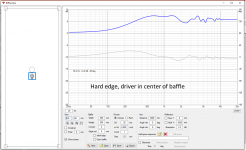
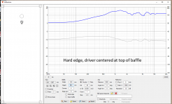
This can be seen in the baffle simulations attached. I simulated a 10 inch x 26 inch baffle with a 1 inch dome tweeter at various locations. With a hard edge (radius = 5mm), there is a ragged response no matter where the tweeter is located. To be fair, there are some specific baffle locations which smooth out considerably, but just a few "magic spots". Next I simulated the same baffle but with a 35 mm radius. Now it does not seem to matter where the driver is located. The low-end of the tweeter is mildly affected by the different baffle steps, but the raggedness of the upper response is gone.
If a baffle has sufficiently radiused edges, much of the negative diffraction effects are minimized.
This can be seen in the baffle simulations attached. I simulated a 10 inch x 26 inch baffle with a 1 inch dome tweeter at various locations. With a hard edge (radius = 5mm), there is a ragged response no matter where the tweeter is located. To be fair, there are some specific baffle locations which smooth out considerably, but just a few "magic spots". Next I simulated the same baffle but with a 35 mm radius. Now it does not seem to matter where the driver is located. The low-end of the tweeter is mildly affected by the different baffle steps, but the raggedness of the upper response is gone.
Attachments
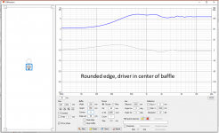


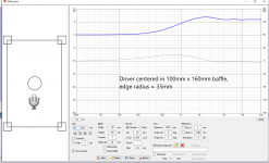
Another couple of examples of baffles with big edge radius.
The first is a 100 mm x 160 mm, with the driver in the center. There are vitually no negative diffraction effects. Playing with the simulation showed that the response stays virtually the same no matter where the driver is located on the baffle.
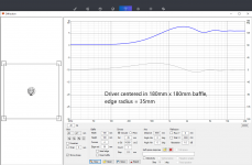
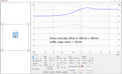
The second has the driver centered in a square baffle 180 mm x 180 mm. Being in the middle of a square baffle should be a poor design, but the response is nice except for a 1 dB dip at 4k.
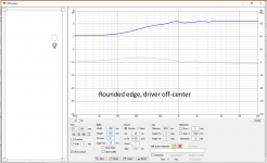
The third shows what happens to a square baffle is the driver is vertically moved off of center. It does not take much offset to improve things, and almost any location not in the exact center results in response that looks like this.
The first is a 100 mm x 160 mm, with the driver in the center. There are vitually no negative diffraction effects. Playing with the simulation showed that the response stays virtually the same no matter where the driver is located on the baffle.
The second has the driver centered in a square baffle 180 mm x 180 mm. Being in the middle of a square baffle should be a poor design, but the response is nice except for a 1 dB dip at 4k.
The third shows what happens to a square baffle is the driver is vertically moved off of center. It does not take much offset to improve things, and almost any location not in the exact center results in response that looks like this.
Attachments
@ puppet, let's be clear that your question revolves around the idea of allowing diffraction in either a narrow or wide cabinet (as opposed to mitigating it either way). In this case the argument has many facets, some are better for wide, and some for narrow. There's the 1ms rule, the precedence effect, the frequency down to and the distance which they hold the wavefront and reduce diffraction, the angle it comes from etc. etc.
Secondly, the frequency below which the sound is headed for the room walls, is a different situation to some degree.
hifijim has shown what a roundover should do, probably also addresses markbakk regarding my earlier comment.
@markbakk a lack of negative diffraction effects is considered a part of what gives a clean image.
Diffraction and baffle step can be simulated of course. Jim's sims prove my point that a non symmetrical placement is beneficial for the on-axis response. Even with rounded or beveled edges by the way. And that makes perfect sense.
I didn't state that I could not argue why less diffraction would lead to better imaging. I stated I couldn't think of any reason why symmetrical placement would give better imaging than asymmetrical placement (Bagby's findings).
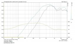
As for point symmetry: long ago I measured some tweeters without mounting them into the baffle. Two venerable Vifa units with round faceplates, if anyone cares. The 20mm dome was remarked for it's linearity by the way.
The attached result shows some things: the diffraction effect clearly leads to a ripple of more than 6dB, the summing and cancellation are quite visible, especially in the response plot of the 20mm. The 26mm dome shows the same, and even the phase behavior of this one (plotted) is slightly altered.
The problem with diffraction is that we cannot compensate for it in the crossover. Of course you can get the on-axis response right, but the off-axis response degrades.
Imho this all ends into this: roundover or bevel baffle corners where you can. And do decide whether you listen on-axis or off-axis (toed in). If on-axis, consider asymmetrical placement, because you don't have to fiddle as much to get a linear response (which will compromise the power response too). I even think that, with well-chosen driver placements, the response above the initial 'bump' becomes pretty linear.
I didn't state that I could not argue why less diffraction would lead to better imaging. I stated I couldn't think of any reason why symmetrical placement would give better imaging than asymmetrical placement (Bagby's findings).
As for point symmetry: long ago I measured some tweeters without mounting them into the baffle. Two venerable Vifa units with round faceplates, if anyone cares. The 20mm dome was remarked for it's linearity by the way.
The attached result shows some things: the diffraction effect clearly leads to a ripple of more than 6dB, the summing and cancellation are quite visible, especially in the response plot of the 20mm. The 26mm dome shows the same, and even the phase behavior of this one (plotted) is slightly altered.
The problem with diffraction is that we cannot compensate for it in the crossover. Of course you can get the on-axis response right, but the off-axis response degrades.
Imho this all ends into this: roundover or bevel baffle corners where you can. And do decide whether you listen on-axis or off-axis (toed in). If on-axis, consider asymmetrical placement, because you don't have to fiddle as much to get a linear response (which will compromise the power response too). I even think that, with well-chosen driver placements, the response above the initial 'bump' becomes pretty linear.
Attachments

Signal lost
bansuri
celef
markbakk
Dave Bullet
bradleypnw
puppet
hifijim
AllenB
markbakk
Wow, thanks! It's great orientation and technical detail to get started with.
Of course, good answers beg more questions so . . . . . .
I want to avoid the need for digital processing, would it make sense to put each driver of an experimental 3 way or 4 way system into its own enclosure? If so how to approach baffle width to support hand-off to the driver below or above at the respective crossover frequency?
I ask after seeing a friend build a 4 way system with good drivers that once done needed heavy digital processing to make it work. In his words it makes no mistakes. In my words it sounds lifeless. My sense is that it would have been smart to get each of the drivers into an enclosure that is optimal for that driver first before trying to congregate them all into a single box.
Again, I have to say thanks. I doubt that any of you have the slightest idea how much help your posts are.
Testing and measuring in boxes instead of the baffle/box with dimensions and shape (in3D) of final construction will lead to trouble. Baffle is fundamental basis for radiation, spl and dispersion, as well as drivers chosen.
Prototyping and measuring will help you to understand all this complexity. Every loudspeaker is a composition of compromises anyway! A long and winding road...
Please study Vituixcad simulation program and it's manual carefully. Check also various threads about it, it's not a piece of cake!
Prototyping and measuring will help you to understand all this complexity. Every loudspeaker is a composition of compromises anyway! A long and winding road...
Please study Vituixcad simulation program and it's manual carefully. Check also various threads about it, it's not a piece of cake!
Hearinginspace, if you have an idea in mind for your loudspeaker, a wish list so to speak, look at what other designers have done. It's a great window into the "what/why's" they did certain things during the design phase. You might find something really close to your wish list, or something that is close and flexible. Tailor it to your tastes.
As Juhazi wrote, you would than need to measure your creation and tweak it accordingly.
GL with your build.
As Juhazi wrote, you would than need to measure your creation and tweak it accordingly.
GL with your build.
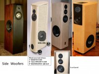
Woofers can be mounted on the side panel to maintain a modest front baffle width or an artistic shape. Side mounting can support one large diameter woofer, or two side-side counter-force woofers. The 12" SB34NRX75-6 is designed for -F3 under 40Hz in a modest sealed volume. A pair of side-side SB23NBACS45-8 8" Aluminum cone woofers in sealed volume generate excellent transients--- sealed 1.6cuft for each woofer. -F3 ~44Hz. (-F3 ~47Hz in sealed 1.3cuft)
B&W engineering strives for the best function and creates several artistic form models before a final product. B&W top Nautilus 802 D3 uses a 6" diameter cone midrange mounted in a 10.5" diameter sphere. Reducing edge diffraction distortion is very important to creating a natural soundstage, and B&W selected the 10.5" diameter.
B&W engineering strives for the best function and creates several artistic form models before a final product. B&W top Nautilus 802 D3 uses a 6" diameter cone midrange mounted in a 10.5" diameter sphere. Reducing edge diffraction distortion is very important to creating a natural soundstage, and B&W selected the 10.5" diameter.
Attachments
- Home
- Loudspeakers
- Multi-Way
- Starting enclosure design with the Baffle