Hello Everyone,
With much help from Wonderboy, I am on my way with building my first preamp. I owe a huge thank you to him and his patient help in tons of topics and questions. I had no idea this process would have been so complex.
WB suggested that I start an open thread to discuss my build as other people could benefit from it. So here I am....
As a status: I have the 5687 Aikido almost built, except for a few nits. My PS-3 power supply came from glass-ware missing some parts, and am awaiting a response from them.
WB, said that a major problem that DIY's get into is that there outputs develop a 'hum'. So, I'm trying to be very careful with how I place components and run wires.
In regard to the dreaded 'hum', I some questions of how to handle chassis and signal grounds? Specifically:
-- In reading the manuals, it seems like the best way to treat signal and chassis grounds is:
1.) Hook the power plug ground to chassis ground.
2.) Bring all signal grounds to a single "signal ground" location. This then includes:
-- Ground for the Aikido 5687 board.
-- Ground for the Glass-ware's PS3 board.
-- Ground for each of the RCA shields. (Note: This would mean that I run two wires from each RCA shield. One to the Signal ground and the second to the Aikido board (along with a second wire that is attached to the center conductor of the RCA)
3.) Then tie Signal ground to Chassis ground using a 10 ohm resister and .01 uf capacitor.
Do I have this correct? The Aikido manual called this the "absolute-Star" grounding scheme.
Thanks so much for your help!
Best Regards,
Stan
Last edited:
the best way to treat signal and chassis grounds is:
1.) Hook the power plug ground to chassis ground.
2.) Bring all signal grounds to a single "signal ground" location. This then includes:
-- Ground for the Aikido 5687 board.
-- Ground for the Glass-ware's PS3 board.
-- Ground for each of the RCA shields.
3.) Then tie Signal ground to Chassis ground using a 10 ohm resister and .01 uf capacitor.
Do I have this correct? The Aikido manual called this the "absolute-Star" grounding scheme.
Thanks so much for your help!
Best Regards,
Stan
I've built a few amps and Aikido stages. Here is what I do.
1. ground the chassis to the safety ground right where the cord comes into the chassis.
2. Run a ground bus from the PSU first filter cap ground, (or the PSU board Ground) to an area around the input rca jacks. I set this up so that these points are as far from each other as possible.
3. The end of the ground bus, near the inputs, is connected to the chassis as you described but I parallel the cap, resistor and two cheap diodes wired the opposite directions.
4. The various stages are linked to the bus in order, psu, then second aikido stage, then first aikido stage, then volume control, then input and output rca jacks.
5. I lift the heaters as Broskie describes.
You should be golden. The Signal ground is tied to the chassis in a single spot. I think of the safety ground connection as a separate thing. If you use two chassis make sure to link them together with a wire.
Athos
Last edited:
I've built a few amps and Aikido stages. Here is what I do.
1. ground the chassis to the safety ground right where the cord comes into the chassis.
2. Run a ground bus from the PSU first filter cap ground, (or the PSU board Ground) to an area around the input rca jacks. I set this up so that these points are as far from each other as possible.
3. The end of the ground bus, near the inputs, is connected to the chassis as you described but I parallel the cap, resistor and two cheap diodes wired the opposite directions.
4. The various stages are linked to the bus in order, psu, then second aikido stage, then first aikido stage, then volume control, then input and output rca jacks.
5. I lift the heaters as Broskie describes.
You should be golden. The Signal ground is tied to the chassis in a single spot. I think of the safety ground connection as a separate thing. If you use two chassis make sure to link them together with a wire.
Athos
There are two basic grounding topologies: star and bus grounding. Broskie chose the star method. The one in quotes is the bus method. Both work so just chose one to get familiar with and then use that for your build. Don't mix them whatever you do as you'll just confuse yourself. How do I know about that? There is a subgroup in the star method called the "star of stars", (reality show spinoff), because sometimes you just can't get everything into one star point. I think that might be what Broskie was referring to when he said "absolute star grounding", i.e., not star of stars.
Here's a handy reference for grounding in general http://www.diyaudio.com/forums/diya...udio-component-grounding-interconnection.html
cheers
I would also make sure to go input > selector switch > pot > Aikido board > output.
Lay out your chassis accordingly. Also as far as grounding, I ran my input ground from the RCAs to the board. Then I also ran a set from the pot to the same input lugs on the board. If you have multiple inputs just connect them in series. Then for the outputs it is one ground and signal wire per channel to the output.
The seems to be the most streamlined wiring method.
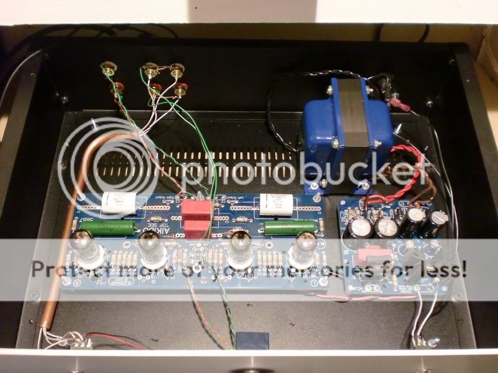
In my layout below I ran the earth ground from the IEC inlet to a lug under the power transformer. Then the PS-3 is grounded via a small jumper to the chassis as well. This could be the best chance at creating a ground loop but mine is dead silent. To improve I could run the earth ground over to the PS-3 where the ground jumper is. There is a single ground wire running from the PS-3 to the Aikido.
Lay out your chassis accordingly. Also as far as grounding, I ran my input ground from the RCAs to the board. Then I also ran a set from the pot to the same input lugs on the board. If you have multiple inputs just connect them in series. Then for the outputs it is one ground and signal wire per channel to the output.
The seems to be the most streamlined wiring method.
In my layout below I ran the earth ground from the IEC inlet to a lug under the power transformer. Then the PS-3 is grounded via a small jumper to the chassis as well. This could be the best chance at creating a ground loop but mine is dead silent. To improve I could run the earth ground over to the PS-3 where the ground jumper is. There is a single ground wire running from the PS-3 to the Aikido.
Stanley, as mentioned, there are 2 approaches, bus ground & star ground.....
A couple of misc. points:
For your power cord chassis ground, use a large stud (or use a screw to make a stud) into the bare chassis metal (#10 screw or so), a crimped ring lug on the ground conductor, and star lock washers above & below the ring, then the nut. The idea is that the star washers will dig in & upset the mating surface materials providing a non-corroding very conductive contact for years to come. This gets close to what UL looks for in commercial electronics. If the chassis is anodized or painted, remove the coating around the stud. This is the most important connection in the unit as far as safety goes.
If possible, use one stud for the chassis ground & the signal ground, then everything is truly grounded at one point. Sometimes due to layout constraints you end up with two separate grounds. Use internal or external star lock washers between all of the ring lugs, the chassis & the nut.
In several of my builds, proper grounding of the volume pot made a huge difference in hum levels, so don't hesitate to experiment. Broskie also should have a jumper on the PCBs to ground them through their mounting holes or let them float. Again experimenting doesn't hurt. There is an Aikido thread on here about hum & grounding for someone's Aikido project; do a search.
If you ground the RCA shields to chassis ground & the PCBs with the ground jumper installed, you may end up with a ground loop, so experiment, since the distal end of the shield will be tied directly to chassis as well as through the PCB mounts.
If you don't have a scope to get an idea of how loud the hum is, use a cheap speaker for your first power up session, and be ready to yank the power in a hurry. It's real easy to let the smoke out of your speakers from hum on the initial power-up (don't ask how I figured this out ) Only move over to your main system once you've got it fairly quiet.
You may want to leave out the ground lift at first, and only add if needed.
EDIT: here's one link for Aikido hum..
http://www.diyaudio.com/forums/tubes-valves/139466-weird-fuzz-aikido-pre-help.html
A couple of misc. points:
For your power cord chassis ground, use a large stud (or use a screw to make a stud) into the bare chassis metal (#10 screw or so), a crimped ring lug on the ground conductor, and star lock washers above & below the ring, then the nut. The idea is that the star washers will dig in & upset the mating surface materials providing a non-corroding very conductive contact for years to come. This gets close to what UL looks for in commercial electronics. If the chassis is anodized or painted, remove the coating around the stud. This is the most important connection in the unit as far as safety goes.
If possible, use one stud for the chassis ground & the signal ground, then everything is truly grounded at one point. Sometimes due to layout constraints you end up with two separate grounds. Use internal or external star lock washers between all of the ring lugs, the chassis & the nut.
In several of my builds, proper grounding of the volume pot made a huge difference in hum levels, so don't hesitate to experiment. Broskie also should have a jumper on the PCBs to ground them through their mounting holes or let them float. Again experimenting doesn't hurt. There is an Aikido thread on here about hum & grounding for someone's Aikido project; do a search.
If you ground the RCA shields to chassis ground & the PCBs with the ground jumper installed, you may end up with a ground loop, so experiment, since the distal end of the shield will be tied directly to chassis as well as through the PCB mounts.
If you don't have a scope to get an idea of how loud the hum is, use a cheap speaker for your first power up session, and be ready to yank the power in a hurry. It's real easy to let the smoke out of your speakers from hum on the initial power-up (don't ask how I figured this out
) Only move over to your main system once you've got it fairly quiet.You may want to leave out the ground lift at first, and only add if needed.
EDIT: here's one link for Aikido hum..
http://www.diyaudio.com/forums/tubes-valves/139466-weird-fuzz-aikido-pre-help.html
Last edited:
- Status
- Not open for further replies.