oh well they won't be turnin' my amp off now I've just been elected club president ( god what have i done?)
Standby Switches are VERY bad with cathode biased amps. Until the cathode bypass cap charges you get a HUGE pulse of current thru' the output tubes. Popped a few HT fuses in one of my amp builds until this finally "clicked" and I deleted the standby switch and replaced it with an output tube grid mute switch.
Hi there do you have more info on grid mute switch, maybe a schematic. just starting a new build which will be cathode bias, wouldn't care too much if it was for my self. but although my friend is a for-nominal guitarist I'm not sure he could even change a valve.😀
Hi Guys
A grid mute is exactly as it sounds: a switch that shorts the grid signal path to ground. Remember, the grid in a cathode-biased amp is already referenced to ground by the grid-leak. You are just shorting this.
For PP you need a double-pole switch.
Have fun
A grid mute is exactly as it sounds: a switch that shorts the grid signal path to ground. Remember, the grid in a cathode-biased amp is already referenced to ground by the grid-leak. You are just shorting this.
For PP you need a double-pole switch.
Have fun
I think, that ArcticBreaze and gingertube meant not to short the control but the screen grid. Then, the valve effectively becomes a triode with lesser transadmittance than a pentode, hence idle current is much reduced.
If you short the screen grid (if the valve has one) to ground then you will get a very loud click when you do it, and another one when you undo it. The control grid will only give you a small click.
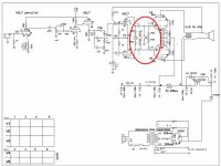
are we talking at crossed purposes here. this is what i think we are talking about😀 may need sum caps on it to get rid of the pop when switched.
this is a new idea to me so i may have it all bollixed up
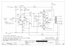
and could sum one please check my VVR circuit too. never done one of those before either, but if it works well I've got 3 more amps here could use one.

this is a new idea to me so i may have it all bollixed up
and could sum one please check my VVR circuit too. never done one of those before either, but if it works well I've got 3 more amps here could use one.
Attachments
The standby switch as implemented in most older amps (CT of power transformer) is a bad thing. It was implemented in early iterations of my SSE amps, and it blew up rectifier tubes and solid state diodes.
Modern power transformers have been cost reduced to the point where they can't be made much cheaper. Hang a scope (with appropriate probe or voltage divider) across the HV secondary of a vintage power transformer in a working circuit and abruptly open the CT connection. Repeat the test several times. You will see a voltage spike that may approach, or exceed the transformer's output voltage. Repeat the test with a modern production transformer (especially a Hammond). You will occasionally see a spike in the 2.5 to 3 KV range! Guess what happens when this spike hits a new production 5AR4? Poof, the lightning bolt jumps around the inside of the tube.
To eliminate this, many amps moved the switch to the DC side of the rectifier. This guarantees an arc every time the switch is opened. How many standby switches have you replaced VS how many power switches, even though the power switch gets used more often?
In the early days of vacuum tube computers it was discovered that tubes that sat idle in the "0" or off state for extended periods of time developed "high interface resistance" "cathode poisoning" or "sleeping sickness." Special cathode formulas were developed to reduce or eliminate this phenomenon, but it is unknown if these coatings were ever used in high power tubes.
It is doubtful that leaving the amp in standby for short breaks will cause significant cathode poisoning, but the switch has no real use.
In a push-pull amplifier, switching idle current should not click loud, because the two impulses, one from each valve, cancel out each other. Also a parallel capacitance somewhere inbetween this switch and power supply should help, as Arcticbreaze reasoned.If you short the screen grid (if the valve has one) to ground then you will get a very loud click when you do it, and another one when you undo it. The control grid will only give you a small click.
They only cancel when the output stage is well-balanced (which it may not be) and if the two poles switch simultaneously (which they almost certainly won't). This assumes a wiping switch action, which doesn't suffer from switch bounce; bounce will make it far worse.Grasso789 said:In a push-pull amplifier, switching idle current should not click loud, because the two impulses, one from each valve, cancel out each other.
OK, in an SE amp you get a very loud click. In a PP amp you may get a slightly quieter click.
Hi Guys
Many European safety agencies disallow standby switches on tube amps and OEMs wishing to market their products in those countries must remove the switch entirely. This should be the case world-wide.
If you really MUST have a standby function that reduces tube power, there are two good ways to do it: screen manipulation and cathode manipulation
Remember that the screen-stop ALWAYS stays tied to the screen. Consider the power-entry-end of that resistor as the switchable element. If we simply break the path to Vs, the tube goes to a very low idle current. making and breaking this connection MAY cause a small pop but nothing to worry about. So, we can add aresistor cross the switch to eliminate this pop if we wish. As we saw in TUT in '95, using a very high value resistance in series with the screen will reduce the idle current as well as short-circuit currents - 100k will do.
We can also break the cathode path with a switch. This leaves the grid tied to the bias supply and the signal entry point. Obviously cathode current will drop to zsero but we may have a leakage current through the grid-bias path and the grid voltage may be pulled positive. This doesn't really matter during the idle condition, but can cause a small surge when the cathode path is reconnected. Again, the fix is to place a resistor across the cathode switch. If we use a value like 10k, we can still get a very small signal from the amp. if you do not want this, then use 100k.
In both cases, Va rises when the tube idle current drops. This will cause all the downstream voltages to rise, too. In both cases, we can still use the preamp to drive other amps if we wish, if there is an effects loop send or just a slave/line out that precedes the PA input.
Muting the grid signal to the output tubes leaves the tubes idling at their normal current, so all the voltages within the amp remain as stock.
When switching DC, it is normal to add a cap across the switch contacts to help assure contact life by reducing arcing. One should also insure that there is a DC path to ground on both sides of the switch. most amps lack proper bleeder resistors unless the builder follows the guidelines of TUT.
Have fun
I am no expert and dunno how to calculate screen grid stuff, but what i know is, that one does not need two poles for switching screen grids of push-pull. Those grids share the same supply and may only have separate series resistors.They only cancel when the output stage is well-balanced (which it may not be) and if the two poles switch simultaneously (which they almost certainly won't). This assumes a wiping switch action, which doesn't suffer from switch bounce; bounce will make it far worse.
Ok, but you are still relying on output stage balance to eliminate the click. Shorting a control grid is better.
Better for muting, but worse for power-saving and prolonging valve life (if wear due to idle anode current is greater than due to cathode heating).
ok starting to get confusing for me again
DF96 which pin on a 6l6 are you calling a control grid that i should short to ground.
i'm not needing to save power and valve life isnt a real issue just need a way to mute the output and keep the tubes warmed up for instant play
PS sorry to have hijacked this thread. But I just want to know the best way to do this, up to now I've been told "standby switches are bad" but no one ever gave me an alternative probably should have been able to work out the screen mute for myself, but just never thought of it.
every valve amp I ever bought had a stby sw so every one I have made has one too.
my new sig should be "stuck in a rut"
When I say "control grid" I mean control grid i.e. grid 1. In most circuits that is the grid where the input signal goes. It is usually grounded for DC, there will be little change when it gets grounded for AC too.ArcticBreaze said:DF96 which pin on a 6l6 are you calling a control grid that i should short to ground.
Hi Guys
How you do grid muting depends on how the amp is biased.
The cross-grid switch gingertube shows above is universally applicable but there might be a little hum from the amp. In a cathode-biased amp you can use a two-pole switch to short both drive lines to ground.
In a fixed-biased amp, you cannot short the grids to ground as that will cause the output stage to melt down. Instead, you split the coupling caps into series pairs and shunt the junctions of the pairs to ground. This provides an AC mute for the signal without effecting the DC conditions.
Note that shorting the signal path to ground at ANY point in the amp provides the same muting action. So, you can move to much safer points in the circuit to try things, such as the input to the power amp proper. In all of these other mute points, you only need a single-pole switch.
Basically NEVER short the control grid directly to ground unless you absolutely know what you are doing !
Have fun
thanks for the info guys.
DF96: yip that's what i thought, sumtimes language gets in the way. even when we're all speaking English we call things different names. but we are on the same page after all lol
Struth: thanks for the heads up on fixed the bios issue. just hope I remember that before i melt one down.
most of my amps are cathode bios tho. so if a tube goes away from home and tools can bung a spare in with out too many issues.
- Status
- Not open for further replies.
- Home
- Live Sound
- Instruments and Amps
- Stand-by Switch reduce their useful life