hello everybody,
i just bought a stage line sta-320 pa amplifier. i got it cheap because it goes into "protect" mode just after powering up. i disassembled it, unsoldered all power transistors and checked them for shorts. the result is, that none of them is shorted. the problem is, when i replace the fuses (they were blown) of one channel, the fuses survive (no matter which channel) but when i replace the fuses of both channels, so that the amplifier leaves protect-mode, all fuses blow again. the power rails arent switched. these issues make me think that the problem is in the driver stage. am i right?
i hope you can understand the description of the problem 😀
Attachments
Hi
Nice find
Might be basic -- it is common sometimes to go diving into the technical - lets not right now.
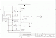
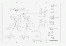
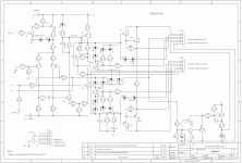
Looking at the schematics -- I noticed that the drive and the power stages are connected by what looks like cabling and connectors
visual inpsection first...
Nice find
Might be basic -- it is common sometimes to go diving into the technical - lets not right now.
Looking at the schematics -- I noticed that the drive and the power stages are connected by what looks like cabling and connectors
visual inpsection first...
- what's the continuity like across that lot of connectors?
- any print broken on PDB - any joint issues?
- what's the condition of the power supply?
Hi
Nice find
Might be basic -- it is common sometimes to go diving into the technical - lets not right now.
Looking at the schematics -- I noticed that the drive and the power stages are connected by what looks like cabling and connectors
visual inpsection first...
- what's the continuity like across that lot of connectors?
- any print broken on PDB - any joint issues?
- what's the condition of the power supply?
right, the driver pcb is connected to the power stage pcb via pinheaders, i resoldered most joints, so they should be okay, also there are no cracks on the pcb. the power supply (two huge transformers, 0-18-60-69 each supply the correct voltages, the filter caps are in good optical condition, i havent unsolodered them so far, because they are glued to the pcb, but i think they are okay too, because after leaving the amp unconnected over night, today there was still about 20V across each rail. i think the reason that the aplifier goes into protect mode is the voltage rail monitor, which measures the voltage AFTER the fuses of each channel. so my next try is to install fuses, so that the protection circuit sees the right voltages, but leave the power stage pcb of the second channel unconnected so it cant blow the fuses...
looking at the schematic again, i see the only thing the control signal does is to activate the LTP-input stage. so for me there is no comprehensible reason that the fuses blow only when the amp goes out of protection...
I( see what looks like a crowbar triac across the output, is it shorted? (There would be a dead short across the output terminals.)
DO you have a variac and a way to monitor mains current draw? You can bring up the mains slowly and look for trends.
This is a solid state amp, it does not need a load. Are you connecting a load during these tests? The simple presence of a load can turn DC offset on the output into blowing fuses. No loads until it is fixed.
An open in a bias string can allow both sides of the push pull to conduct at once, that surely blows fuses.
You have tested the output transistors, good. Now don;t bother to remove them first, but set your meter to diode test, and just go down the board and check every trransistor and diode on it. If it checks shorted, then remove it and retest. If it does n ot check as shorted, then it isn;t shorted. No parallel circuit in the world will make a shorted part look like it is not. Not very high tech nor is it deep troubleshooting, but it might reveal a shorted or open predriver or some such that won;t reveal itself blowing fuses each time.
hmm, i replaced the fuses of one channel, started up and the channel worked. added the other fuses, now both channels are working like a charm... very strange... perhaps only the connection between power supply and power stage board was broken...
thank you two anyway!
thank you two anyway!
It's nice when something comes together 🙂
oh yes, youre right.
but i just realized another problem:
with no load connected i tried what happens when i drive the amp into clipping. i didn't even go into clipping when there was a spark on the power stage pcb near one load balancing resistor oder driver transistor. i turned the volume low again, measured for high voltages on the output and after not finding any i connected a speaker. the amplifier is still working properly as far as i can tell. any idea what this was? only one channel was affected... did it perhaps start oscillating with no load?
Do you have an oscillioscope?
unfortunately i haven't...
Hi, Everyone, New member John here!
Gruni, Do you happen to have a schematic/circuit/shaltplann of the power supply, please? I also have a fuse problem, F6 in my case, this ruptures violently on power up. I would just like to see what F6 feeds before going any further.
Many thanks,
John.
Gruni, Do you happen to have a schematic/circuit/shaltplann of the power supply, please? I also have a fuse problem, F6 in my case, this ruptures violently on power up. I would just like to see what F6 feeds before going any further.
Many thanks,
John.
F6 feeds the power transistors of the right channel. try swapping the driver boards, this helped me with two of the amps. in both amps the control circuit for the output protection triac wasnt working for one channel (this circuit is placed on the driver board)
- Status
- Not open for further replies.
- Home
- Amplifiers
- Solid State
- stage line sta-320 troubleshooting


