I’m adding a shunt notch filter to an existing xo and space is tight. My options are to split the notch filter off on its own, or stack the cap and resistor on top of the coil. Would this cause any issues? It’s for a compression driver after the pad, so very low voltage and likely no heat issues.

Attachments
Great! This would certainly simplify things.
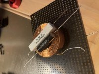
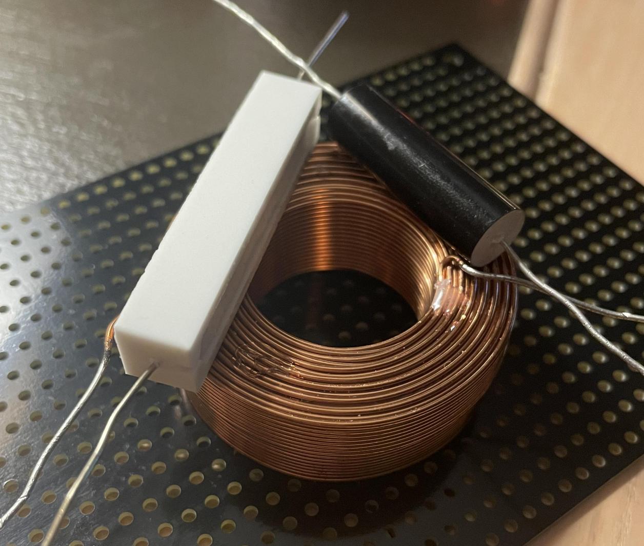
I think this arrangement might work well. I could glue down the coil to the board, then glue the cap and resistor to the coil. Then zip tie around the resistor and cap down under the board.
I rotated the resistor on its side to get the smooth side against the inductor. All inductors are spaced apart and oriented correctly.
That black board was the potential separate board, not the existing xo.
Stupid photos keep rotating sideways.
Attachments

Last edited by a moderator:
Thanks. I'm going to assemble everything outside the box and do some spirited listening and see if anything gets dangerously warm. I haven't noticed any issues yet with my test setup, but it's multiple coils series together at the moment. Just got the single coil to replace my hack job. The final value of the coil and resistor was quite a bit off from the xsim prediction. I wouldn't ever try using a sim for a narrow notch filter again. Needs to be so precise to get the desired results.
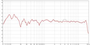
Here is the result with the filter added. Really smoothed things out and took out some sibilance I was trying to get rid of.
In room, 3 feet, 1/12 smoothing

Here is the result with the filter added. Really smoothed things out and took out some sibilance I was trying to get rid of.
In room, 3 feet, 1/12 smoothing
Attachments
The only concern with stacking components together is having magnetic component leads close to inductors, which can create small amounts of distortion in tweeter HP circuits (where its more audible). I'm not saying you would necessarily be able to hear that, but I'm pointing out the possibility of it.
@ Samps, yes I agree that notches should always be tuned in situ. It isn't so much that the simulator is wrong.. even component tolerances can throw these narrow filters off.
@ Profiguy
What's the concern with those, the lead affecting the inductor or the flux invading the lead? Has there been a study done on this?
@ Profiguy
What's the concern with those, the lead affecting the inductor or the flux invading the lead? Has there been a study done on this?
@AllenB I once ran into some strange issues with a crossover that a friend put together for his diy mini monitors. There was a tweeter attenuating resistor that got put into the center of the tweeter HP parallel inductor and it caused the tweeter to have excessively high audible THD at certain frequencies. It sort of mimicked a rubbing VC in the lower mids. When I removed the tweeter and swept it on its own with a sine wave, it sounded fine. I immediately suspected the resistor connecting leads and body's magnetic properties to be altering the inductors behavior, so we rebuilt the crossover on a wooden board and the issue was gone. There were no nearby inductors that could have coupled with that inductor either.
The resistor basically acted like an inductor core that saturated very quickly and in a rather non linear way. It was surprising that it was that audible and I would have never thought it could cause that much of an issue.
The resistor basically acted like an inductor core that saturated very quickly and in a rather non linear way. It was surprising that it was that audible and I would have never thought it could cause that much of an issue.
Wirewound resistors can have serious inductive values, but the low-selfinductance types are so common, that hardly can be an issue. It even is quite good practice in amplifier output stages to wrap some wire for coil around a resistor to create a LP filter.
Do you think there might have been some mutual inductance happening there?
LP coil was 4-5 inches away from the tweeter HP coil and at a 90 degree angle. It was also set up for bi-wiring so the LP wasn't even used for testing.
Wirewound resistors can have serious inductive values, but the low-selfinductance types are so common, that hardly can be an issue. It even is quite good practice in amplifier output stages to wrap some wire for coil around a resistor to create a LP filter.
The end caps on WW resistors are usually steel along with the leads, which do have some mass to them and can act as an inductor core.
Amp output LR series circuits typically are packaged together for convenience purposes to be compact and close to the speaker terminals. They don't need to be that big mainly because the resistor doesn't really see any voltage drop when the amp is reproducing the typical music spectrum as the coil is so small in value. I learned that the hard way as a teenager when I first started working on audio equipment, trying to see how much power bandwidth the amp had at higher frequencies with a sine wave generator and load resistor - the resistor inside the coil started to smoke as I went past 25k or so.... oops!
No, I meant the wirewound resistor with its turns could be linking into the flux created by the inductor etc..
Hmm... never thought of that. The resistor was only around 1 to 2 ohms, so I doubt it could have generated that strong of a field or vice versa pick up anything significant from the inductor.
I put resistors on top of an air coil like that all the time (for a BSC shelf filter). No problems. Just make sure it doesn’t rattle.
This reminds me of similar discovery by GaryM44 that using twist ties to hold down inductors can cause surprising amounts of distortion.…There was a tweeter attenuating resistor that got put into the center of the tweeter HP parallel inductor and it caused the tweeter to have excessively high audible THD at certain frequencies…The resistor basically acted like an inductor core that saturated very quickly and in a rather non linear way. It was surprising that it was that audible and I would have never thought it could cause that much of an issue.
Distorion in MTM build: Post #48
Distorion in MTM build: Post #23
Distorion in MTM build: Post #1
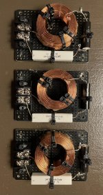
I wasn’t able to follow through with stacking the parts. There ended up not being a way to get the new inductor far enough away from the other inductors and/or oriented the correct way. So I had to use a separate board.
Luckily I had two of the 3x5 boards from PE left over from another project. I cut each of those in half to get the three boards I needed. There was barely enough room, but it turned out pretty nice and compact.
Thanks for the help anyways!

Luckily I had two of the 3x5 boards from PE left over from another project. I cut each of those in half to get the three boards I needed. There was barely enough room, but it turned out pretty nice and compact.
Thanks for the help anyways!
Attachments
- Home
- Loudspeakers
- Multi-Way
- Stacking crossover components?